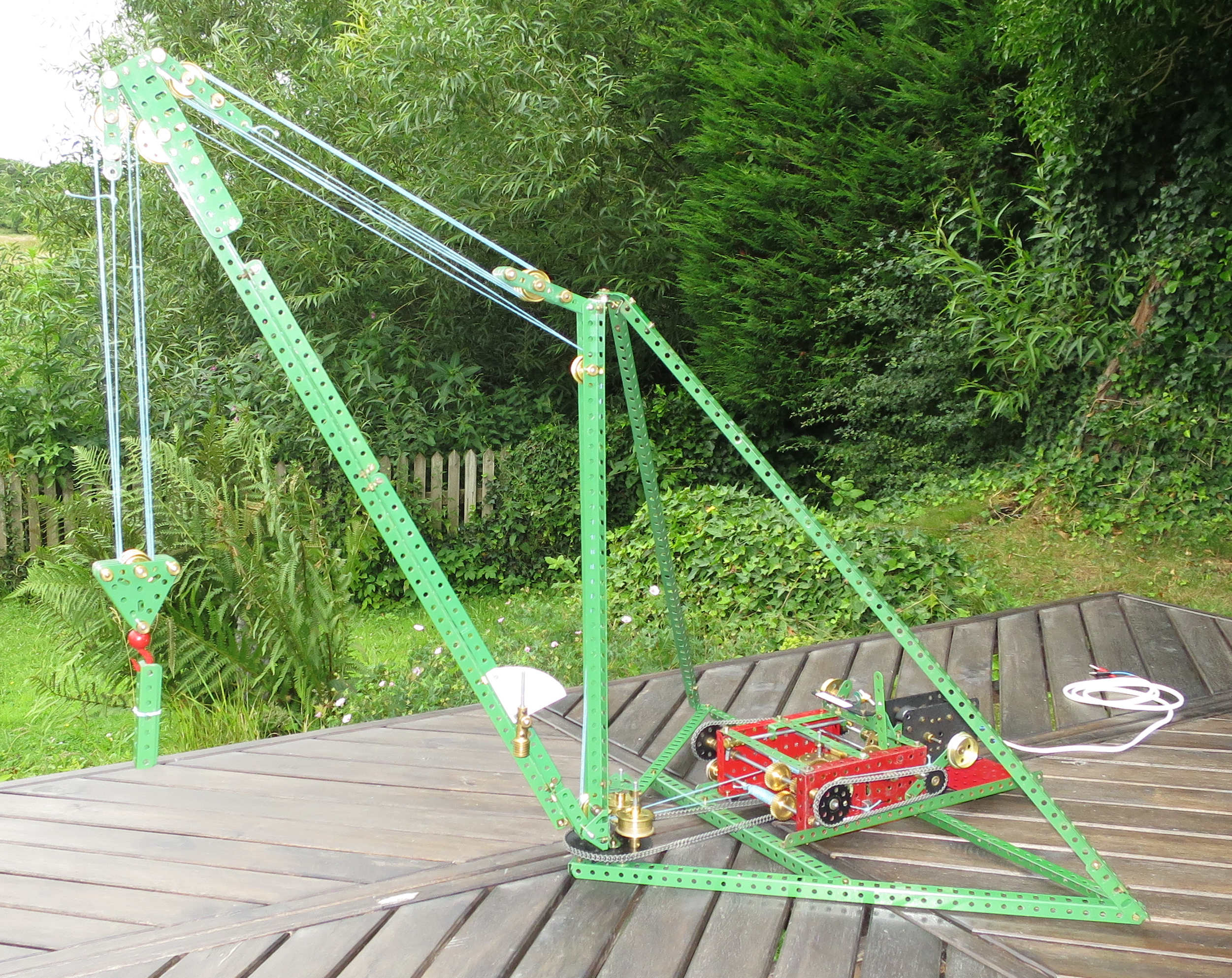
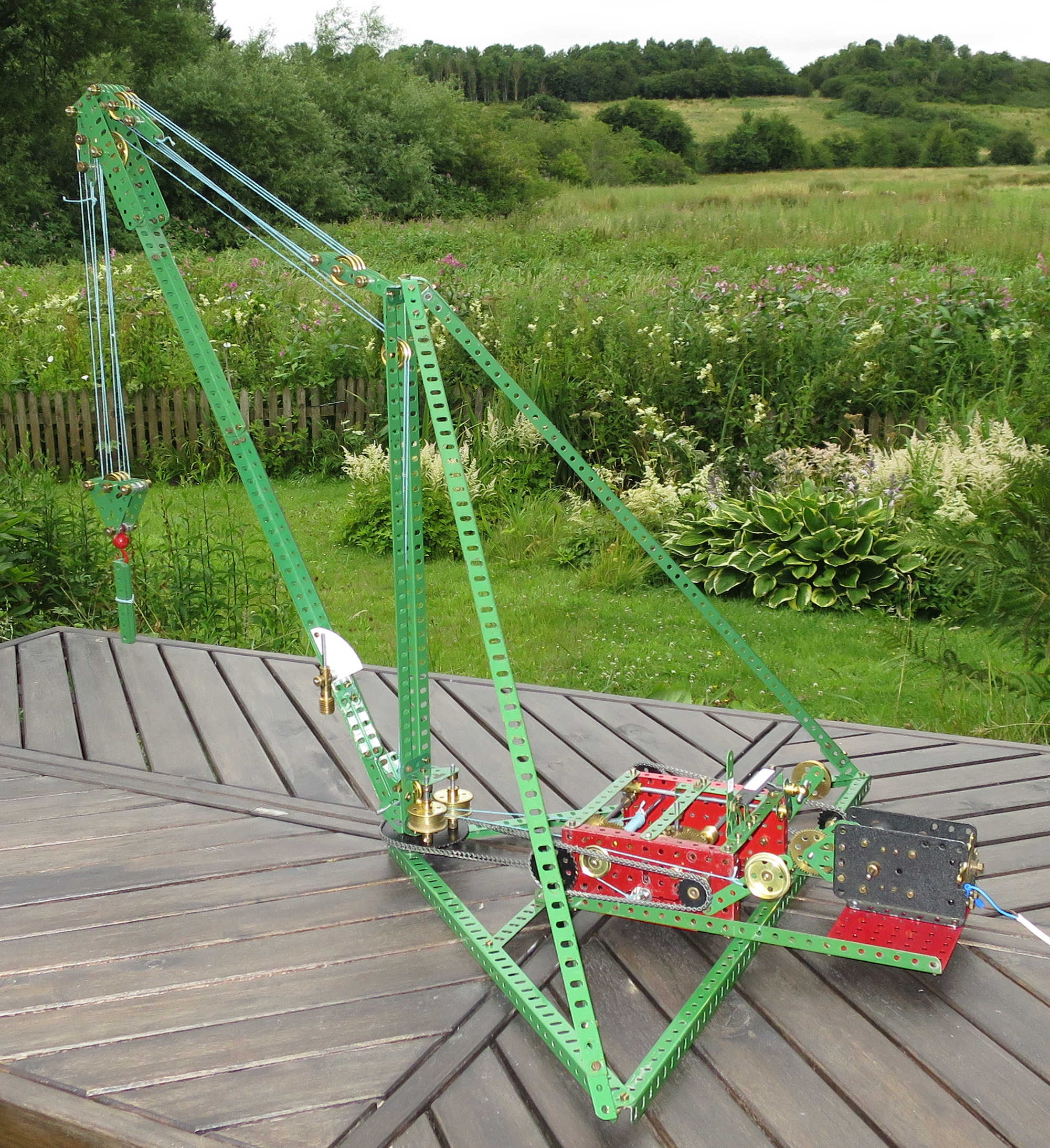
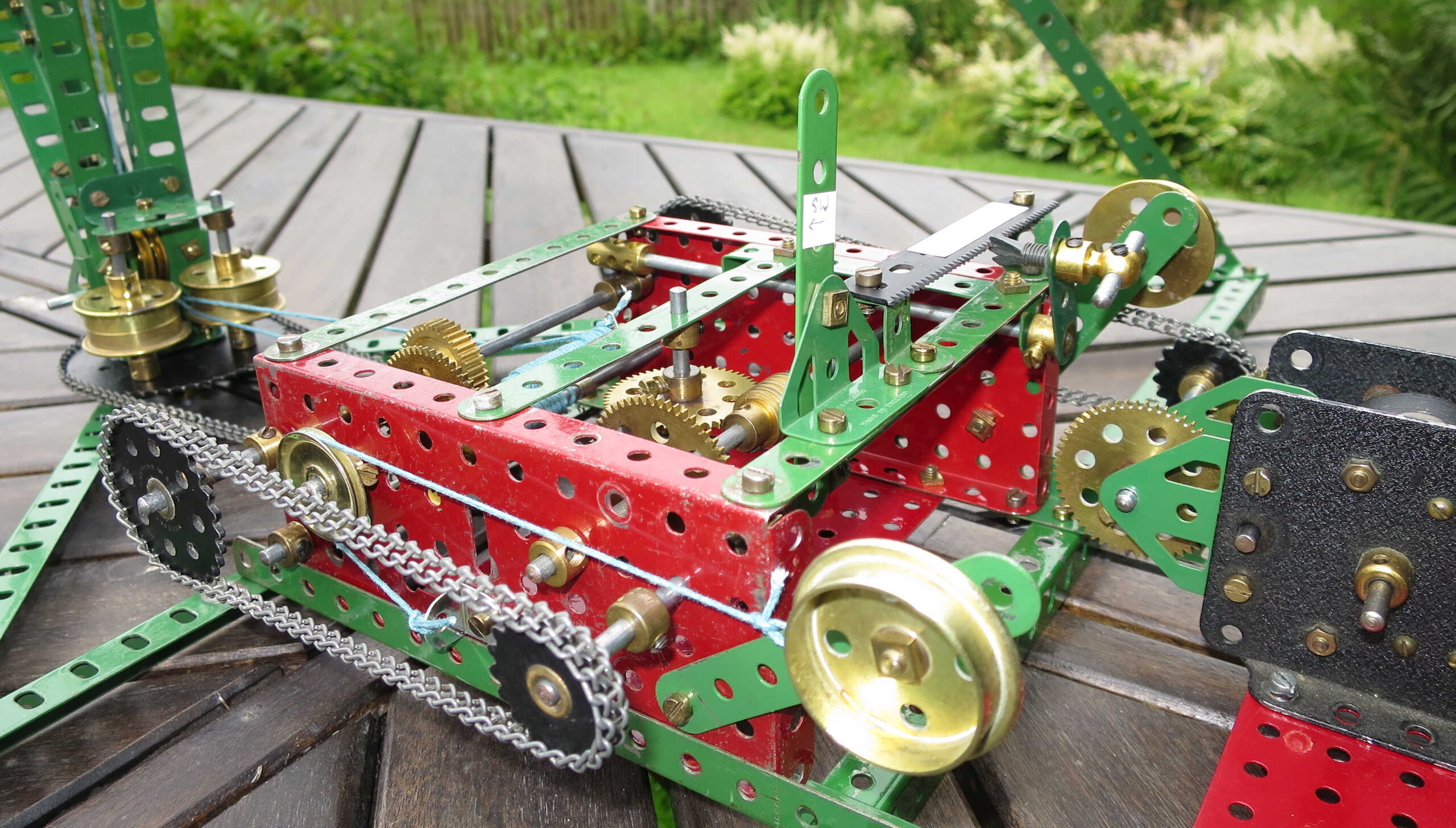
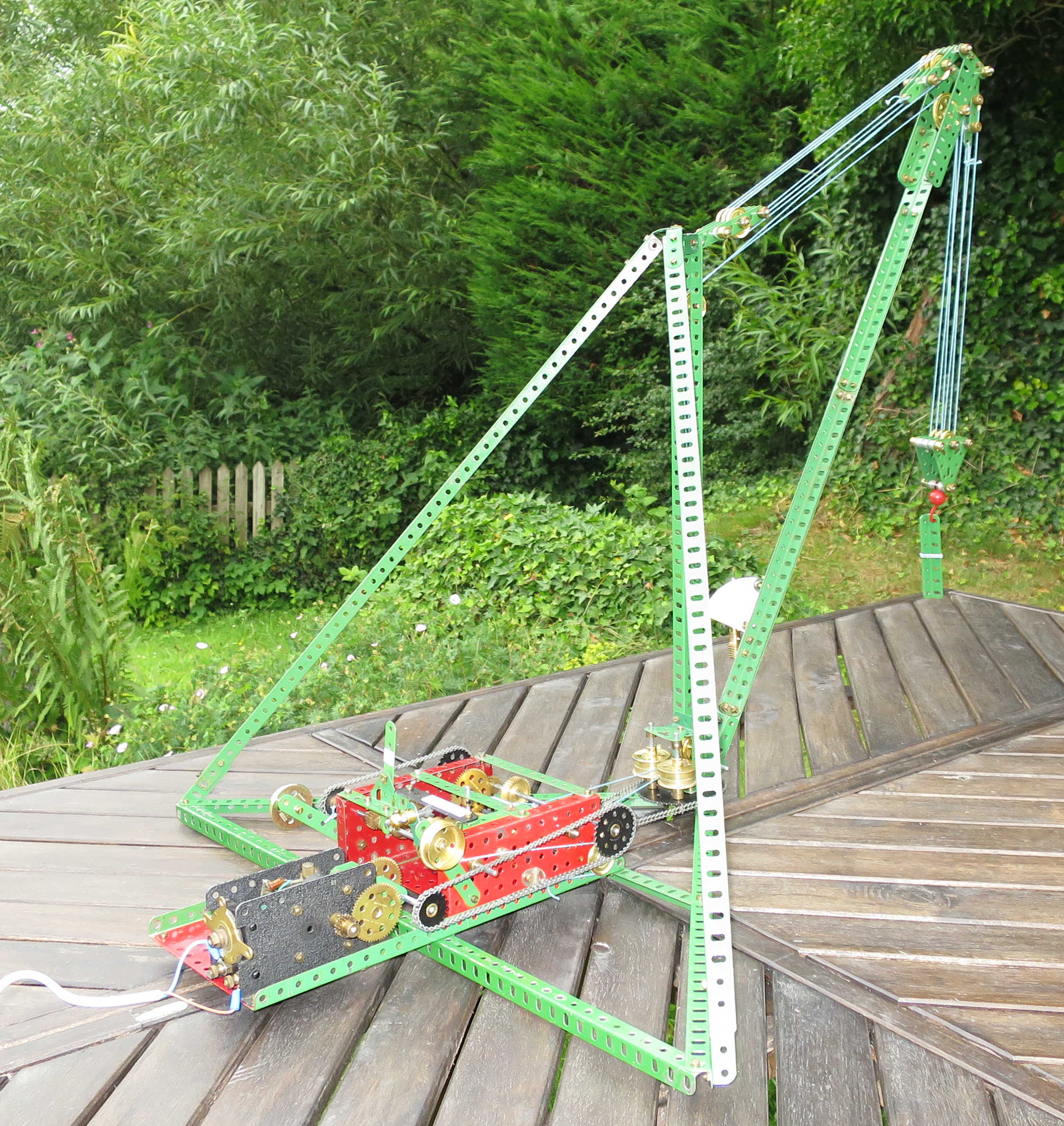
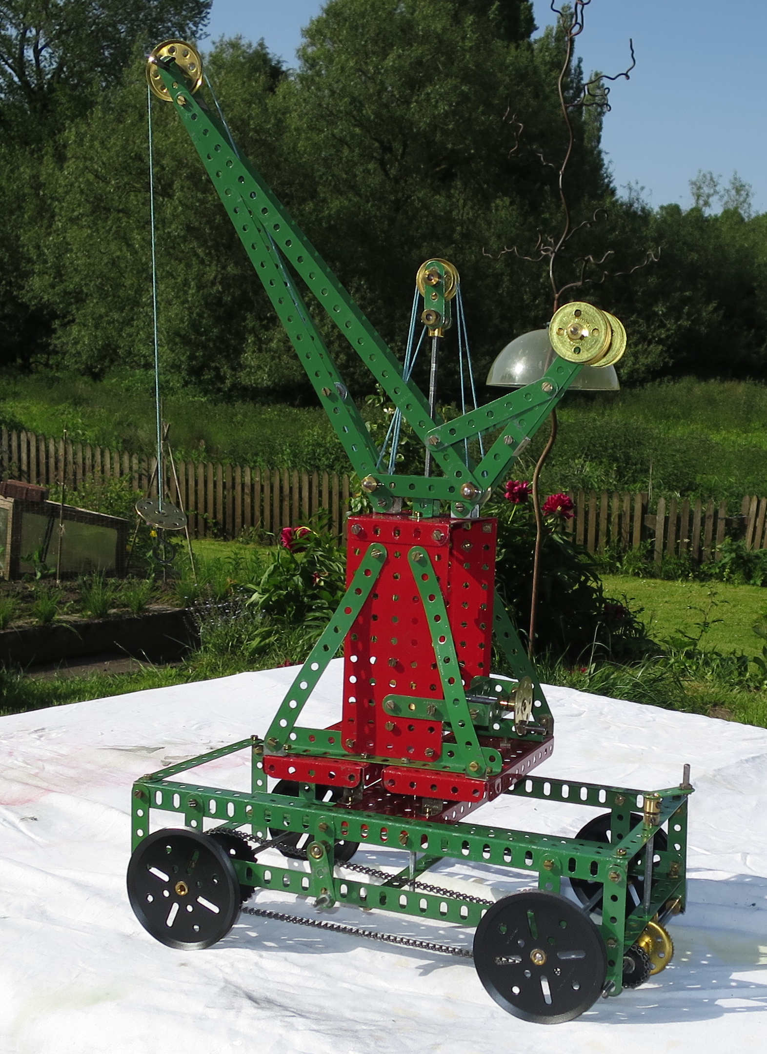
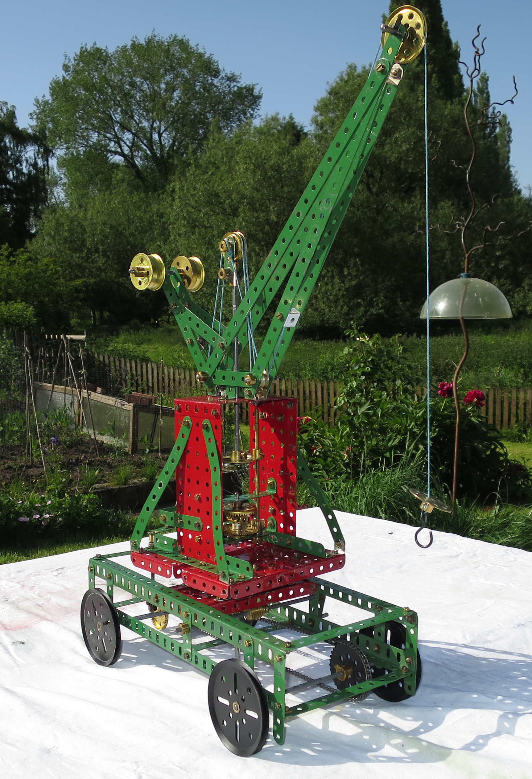
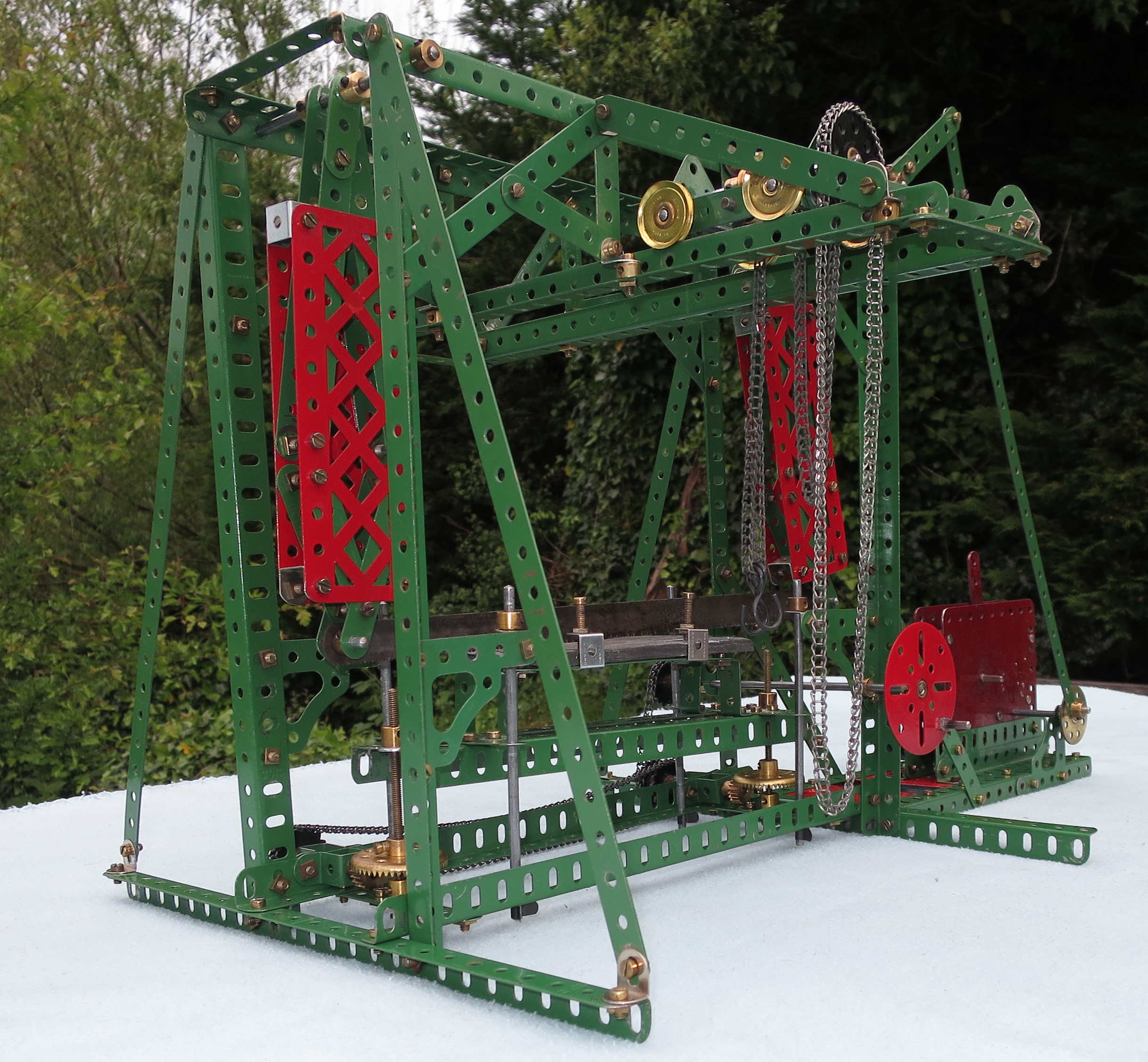
This is Super Model no. 6, and is one of many Meccano cranes. I have to confess I wasn’t really looking forward to building it: in the leaflet it looks very simple and not very impressive. Once built, however, it’s quite an elegant and impressive thing. It’s big, for one thing. What’s more, it works properly – I take my hat off to whoever designed this one.
A smaller version of this model was in the 1916 Meccano Instruction Book 1, and the Super Model version first appeared in 1925. The build instructions were issued in leaflet form from 1928.
The Build
This was reasonably straightforward for a change, and I enjoyed putting it together. Perhaps because it’s a skeletal model, the leaflet pictures show most of the detail you need and there’s relatively little guesswork needed.
As usual the leaflet parts list is incomplete and inaccurate: you need more cogs and sprockets, you need an extra 5 1/2″ strip and four 2 1/2″ angle girders. And the parts for the radius indicator aren’t included in the parts list. On the other hand you don’t need any 3 1/2″ angle girders – the six I had ready I used as a load for the crane instead.
I made one improvement to the gearbox. There are two levers (24 and 26 in Fig. 5) that move rods to change which crane function to engage (rods 16 and 25 in Fig. 5). There’s nothing to stop the levers moving with the vibrations of the motor, and engaging or disengaging cogs when you don’t want that to happen. This is a common problem with Meccano gearboxes, and I’ve fixed it in different ways. This time, it was easy to fix lever 26 by tightening up the bolt fastening it to the trunnion, giving it some friction. Lever 24 needed a bit more thinking about. What I ended up doing was moving lever 26 and the trunnion over by 1″, which made room to mount a short rack strip 1/2″ above and in front of the 5 1/2″ strip (parallel to it), using a couple of reversed angle brackets. The rack strip is there to stop the lever 24 from moving on its own, so I needed the lever to engage intermittently with the rack strip. I put a compression spring onto a centre fork, pushed it through the top hole of lever 24, and fixed a handrail coupling to the fork. This meant I could move the lever by pulling the handrail coupling and centre fork back against the spring, moving the lever sideways, then letting the spring push the centre fork back into a new position on the rack, holding the rod in its new position. A 1″ rod through the handrail coupling made it easier to hold. And I labelled up the three positions on the rack so I’d remember what was what.
Oh, and I used anchoring springs rather than spring clips to anchor the two cords in the gearbox.
For a break from building the Super Models I thought I’d build something with my 1970s Outfit 9. Although I’ve had this outfit since the 1970s, I’ve never built this particular model – number 9.9 in the 1973 Outfit 9 Book of Models. I think I’d been put off by the amount of strip and plate bending required. Having built a few Super Models, I’m now used to bending my Meccano, so this one no longer held any fears for me. I’ve got a strip roller and I’m going to use it.
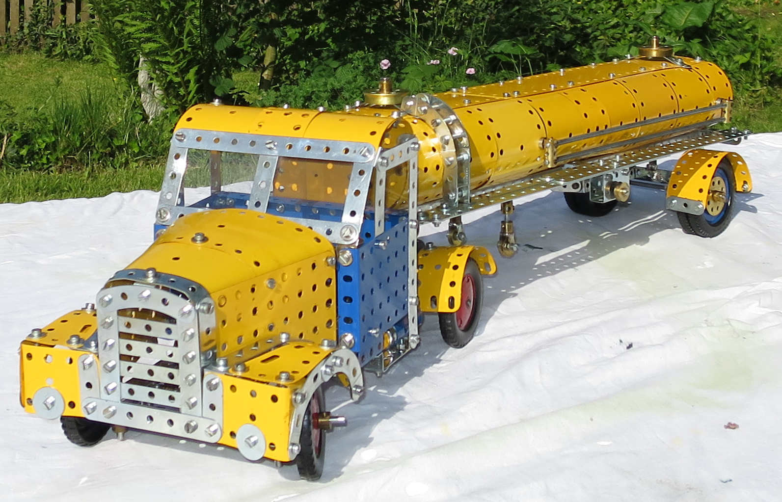
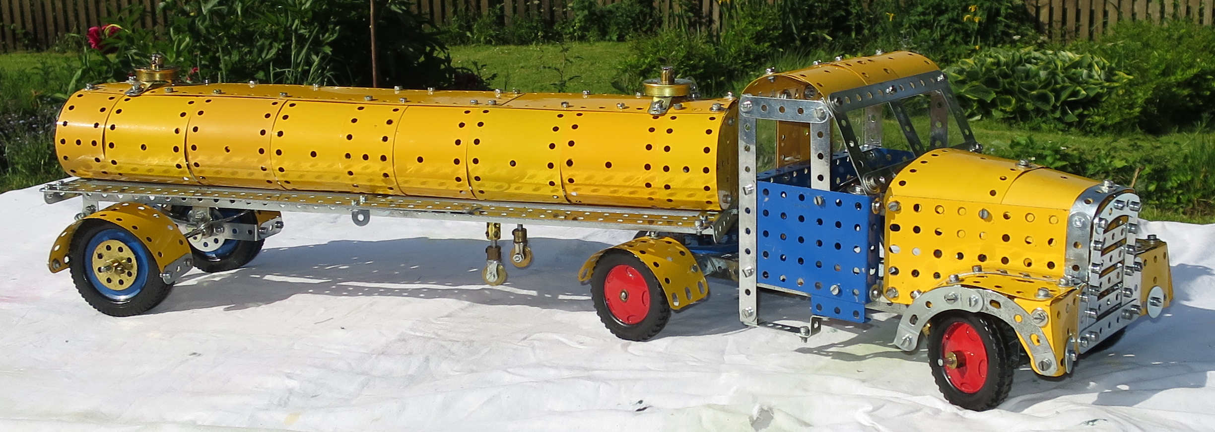
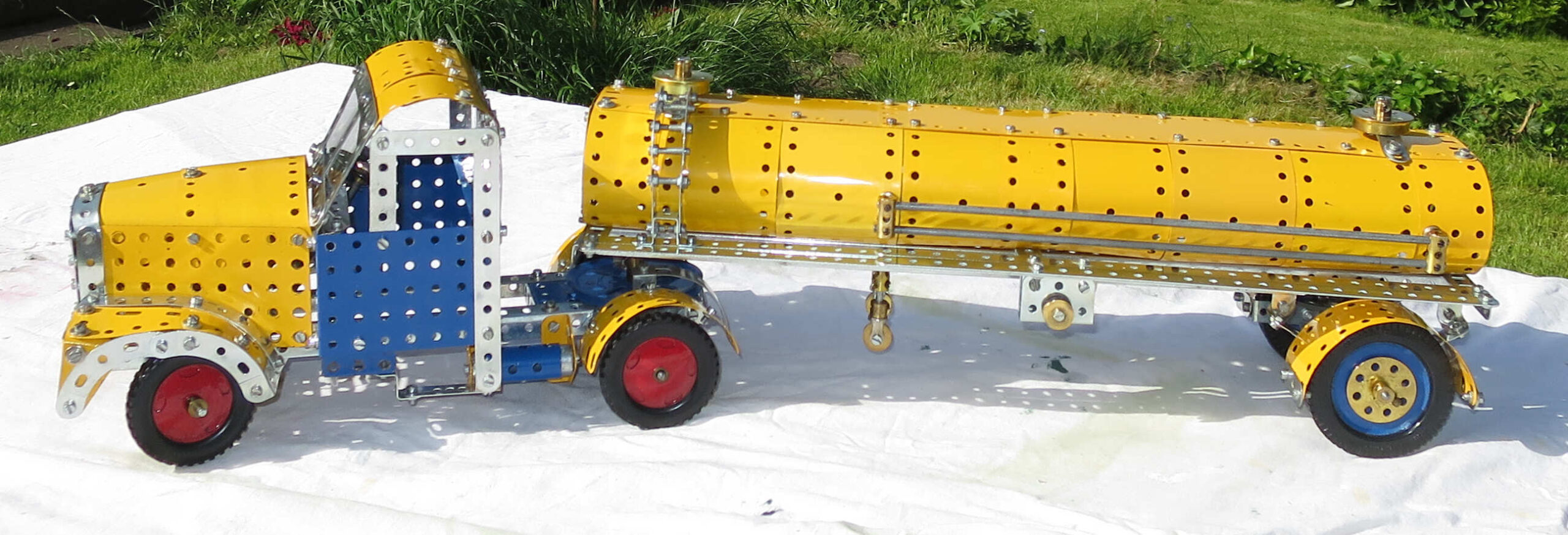
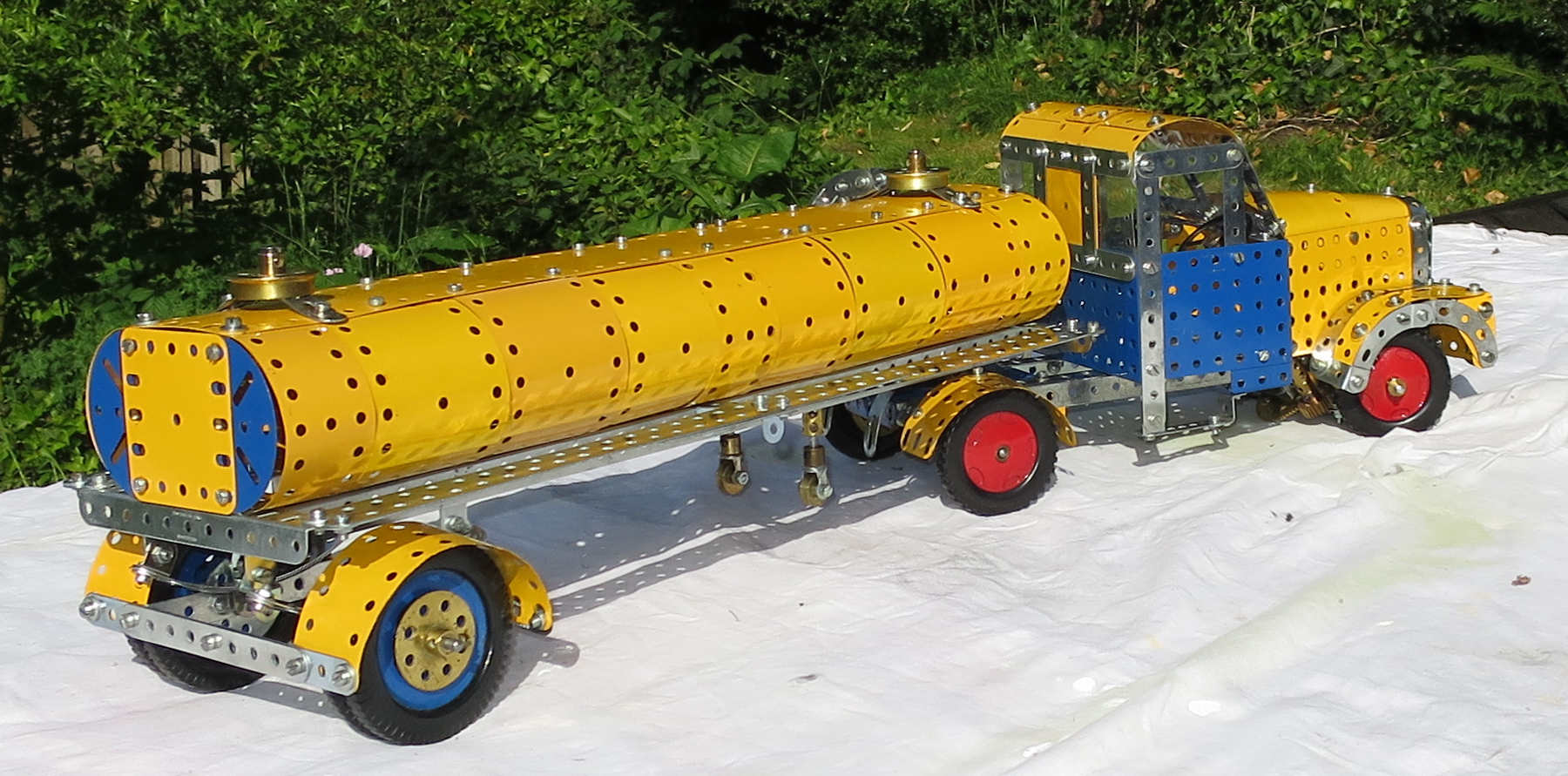
For a 1970s Outfit 9 model, I think it looks pretty good. It’s not motorised, but since there’s no floor to the cab the driver can run along the ground Fred Flintstone-style. It’s got steering (but see below), and the trailer’s even got leaf springs, although they don’t actually spring the trailer – they’re just for show.
Build issues
Firstly, the parts list is seriously incomplete. As long as you’ve got a 1970s Outfit 9 you’ll be OK, but don’t rely on the parts list for this model. I won’t try to list the omissions – there are too many.
Secondly, the steering linkage is really pretty poor. I built it as per the Book of Models, then had to give it some serious improvement to get it to work properly. I replaced the bent 3″ strip (part 4 on diagram) with a 2″ rod and two extra rod and strip connectors (part 212). I ditched the screwed rod, and mounted the gear wheel 27a on a short rod journalled in a 2 1/2″ double angle strip and a double bracket. The double angle strip I bolted to two 1″ triangular plates (part 77), which I bolted to the main girders. This left the gear wheel approximately in the same place as it had been, and far more stable. It didn’t quite mesh with the smaller gear wheel now, but I replaced the 1/2″ gear with a 3/4″ gear, spaced it out from the girder with a couple of washers, and the fit was good. Now the steering was solid enough, apart from the steering column not being journalled in anything at the top. A long bolt through the dashboard and a collar onto an obtuse angle bracket fixed this. Incidentally the steering column is missing from the parts list, requires a 4″ rod according the diagram, and now needed a 4 1/2″ rod after my redesign. (What the anchoring spring and wheel disc were doing in the original design is anyone’s guess. And they weren’t in the parts list either.)
Thirdly, don’t use four obtuse angle brackets to attach the bonnet to the cab, as shown in the diagram. The angle’s completely wrong. You just need to open up four ordinary angle brackets very slightly. This was not fun to go back and fix.
Fourthly, the trailer mudguard assembly wouldn’t fit over the 2 1/2″ by 1″ double angle strips – the mudguards were forced to splay apart. I tried getting the mudguards further apart but there’s little give there. What did work was remounting the angle brackets fixing the springs to the double angle strips so they were inside the strips. It gained about 1/10″ but that’s all it needed.
Fifthly, and finally, getting the trailer’s axle to run freely took quite a bit of work. There is a design problem here. A wheel disc is used to journal the axle, and also to secure the mudguard/axle assembly in place. These two fixings are 1/2″ apart on the wheel disc. The corresponding fixing points on the spring assembly are more than 1/2″ apart – a double bracket, three thicknesses of strip in the spring, and an angle bracket. Even with the long hole on the angle bracket. So the axle won’t run freely. I tried a few possible fixes, and ended up replacing the two double brackets with pairs of angle brackets, journalling the axle in the long holes of the angle brackets. This worked, as long as I didn’t overtighten up the bolts fixing the wheel disc to the angle brackets above the springs. Tightening these bolts twisted something, locking the axle up again. In the end I fixed this by adding washer shims between the wheel discs and the angle brackets.
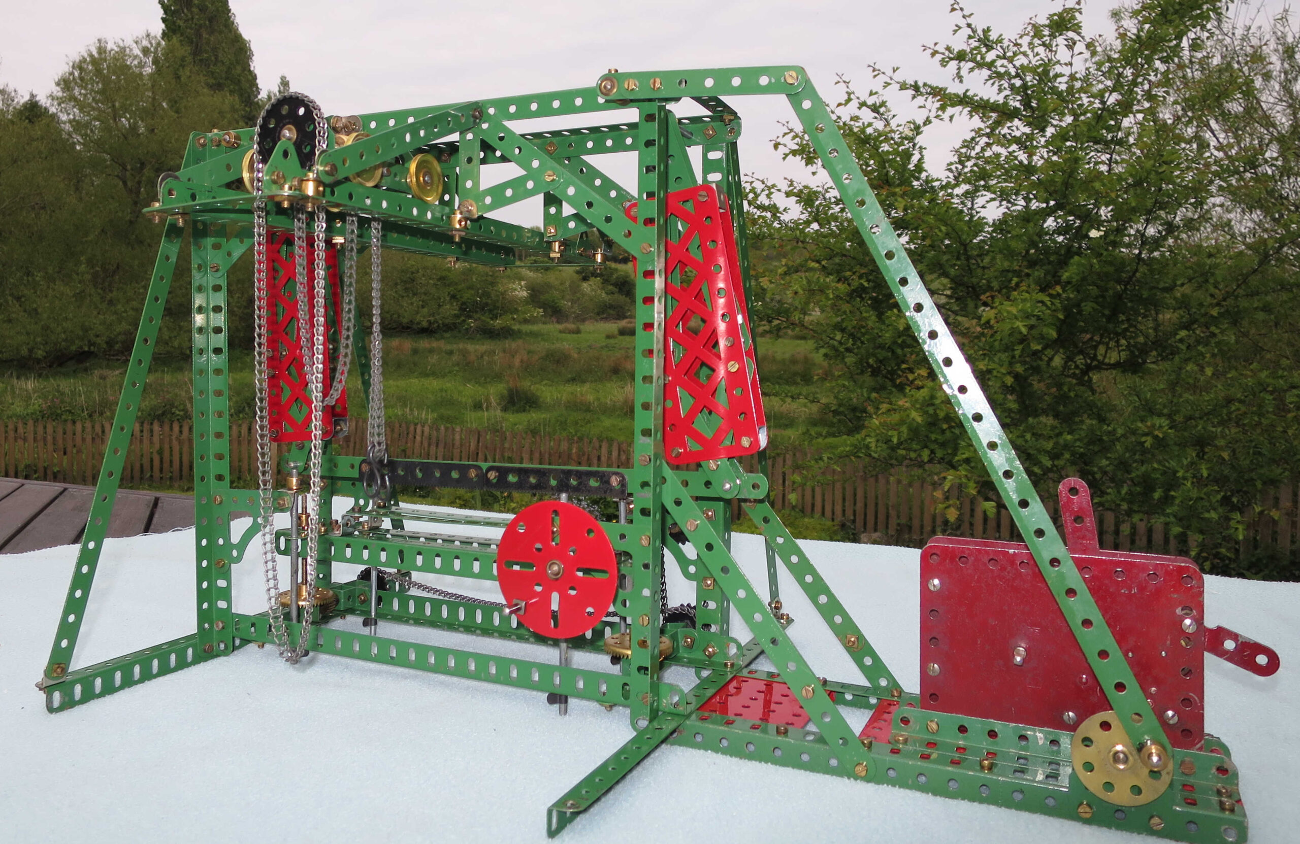
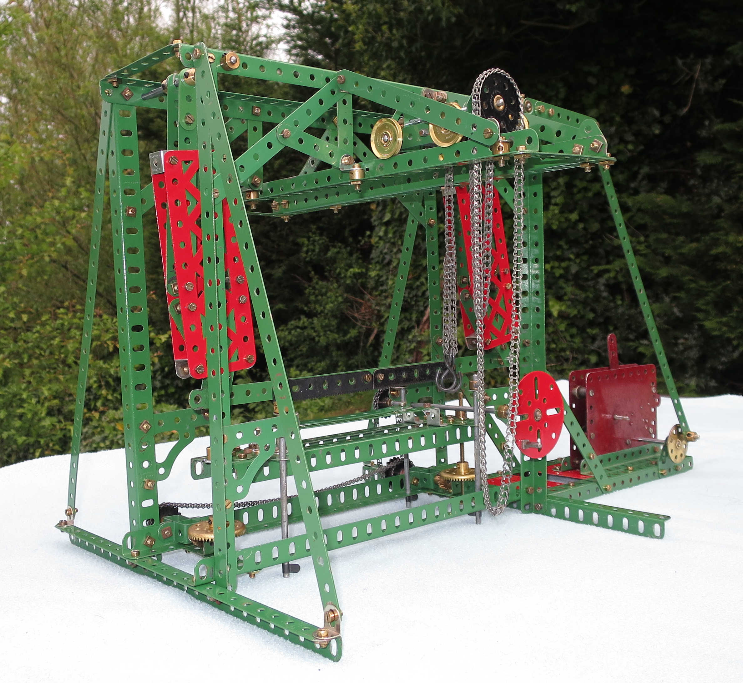
To be honest I just built this one to get it ticked off. I’m trying to build all the 1920s/30s Super Models, and this is one of them – number 25. It’s just not that super. It’s based on a hydraulic-powered crane, but doesn’t really convince as that, since there’s little sign of hydraulics, or anything looking like them. The prototype runs on rails, but the model won’t, as there’s no flanges to the wheels. And it’s not very big and not very complicated. It did, however, win a prize in a Meccano competition, and appeared on the front of Meccano Magazine in the January/February 1921 issue.
I didn’t have any problems with the build really. There are a few things missing from the parts list, as usual, of course. You need a couple of 3/8″ bolts to attach bush wheel 8 (fig. 3) to the cranks 7, and careful adjustment is needed to get the friction on the screwed rods down to a reasonable level. You need a 1″ sprocket, and two 1″ rods. And Fig. 2 shows a 3″ strip vertically at each corner, whereas the parts list seems to assume that two of them are 2 1/2″ strips. Either works though. I also used 6 1/2″ rods for the axles instead of 8″ rods – it looks better that way.
This simple model was included with the old Outfit 7, but wasn’t in Outfit 6. I can’t see why not – the only extra parts needed were two 5″ screwed rods and a third threaded pin. 4 1/2″ screwed rods would work just as well, and they were in Outfit 6. And a long bolt would have substituted for one of the threaded pins. I guess we’ll never know…
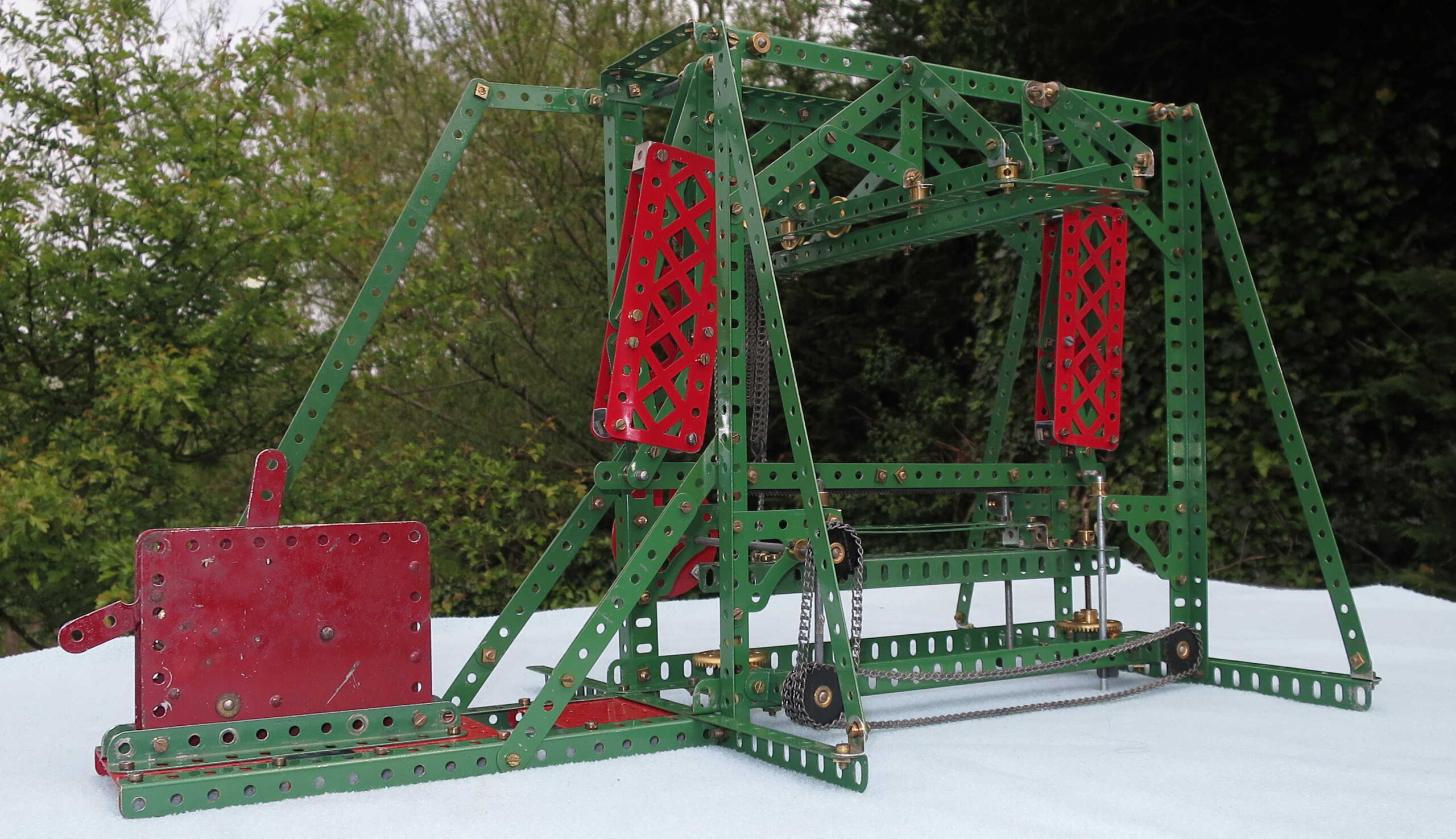
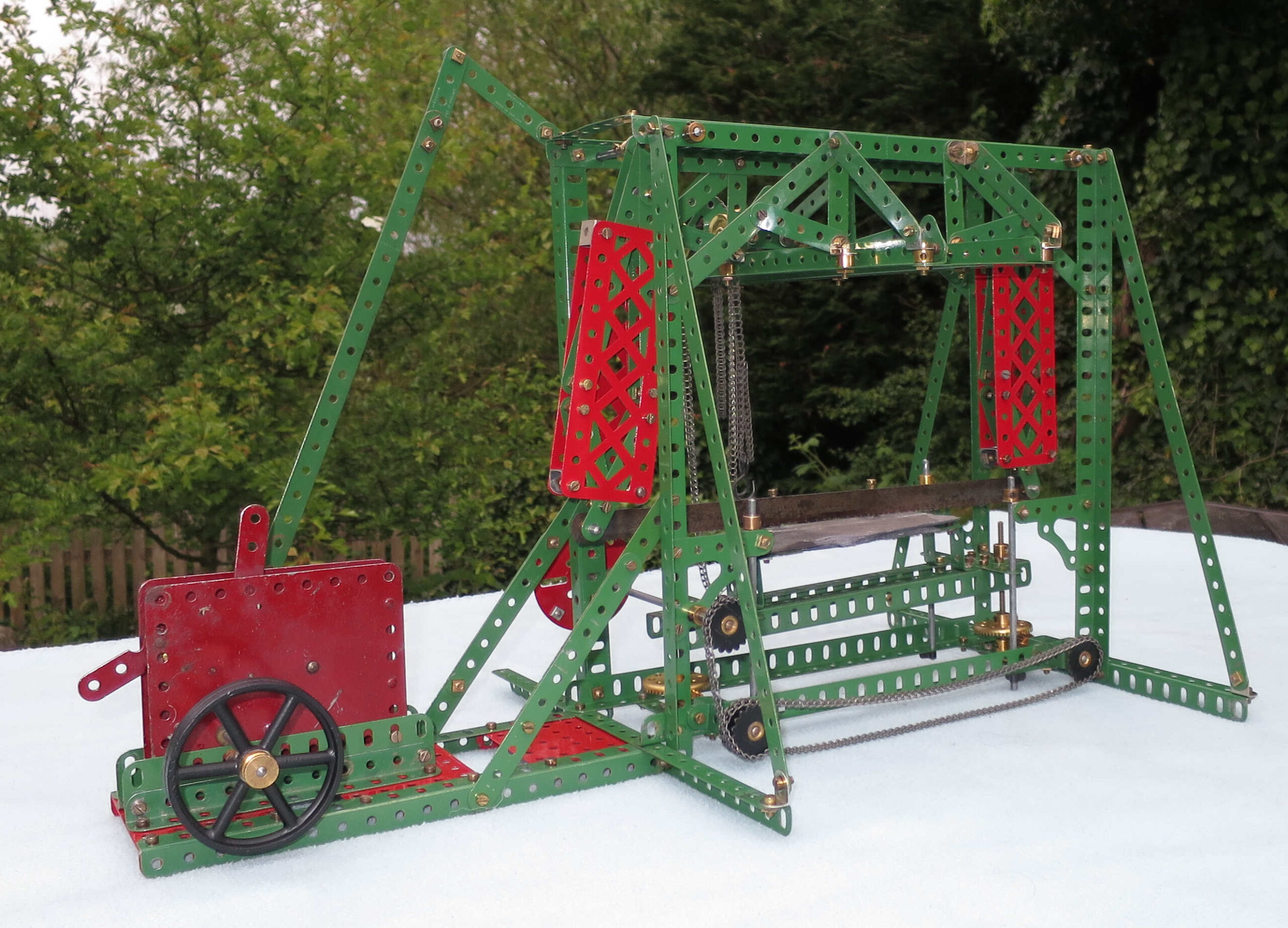
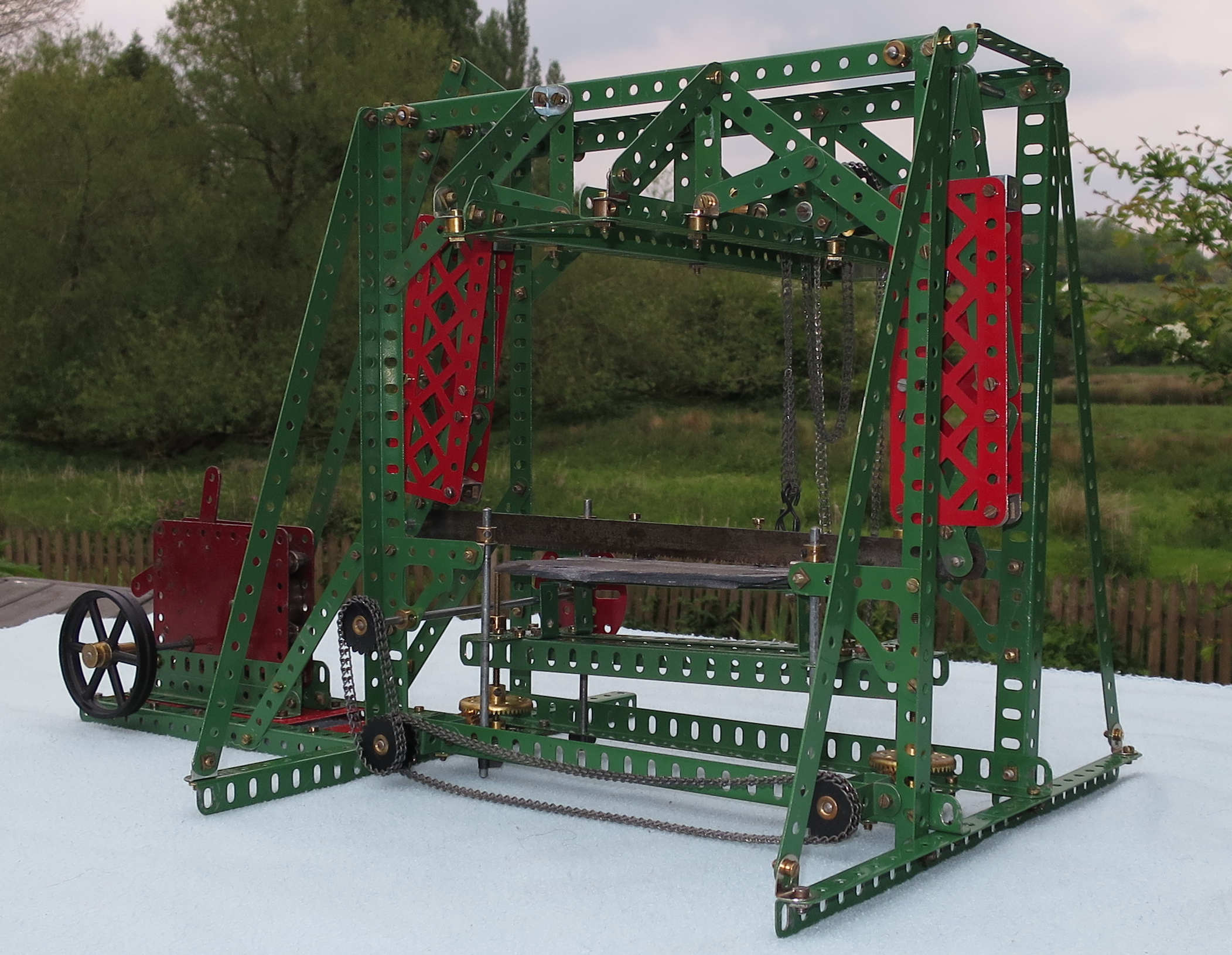
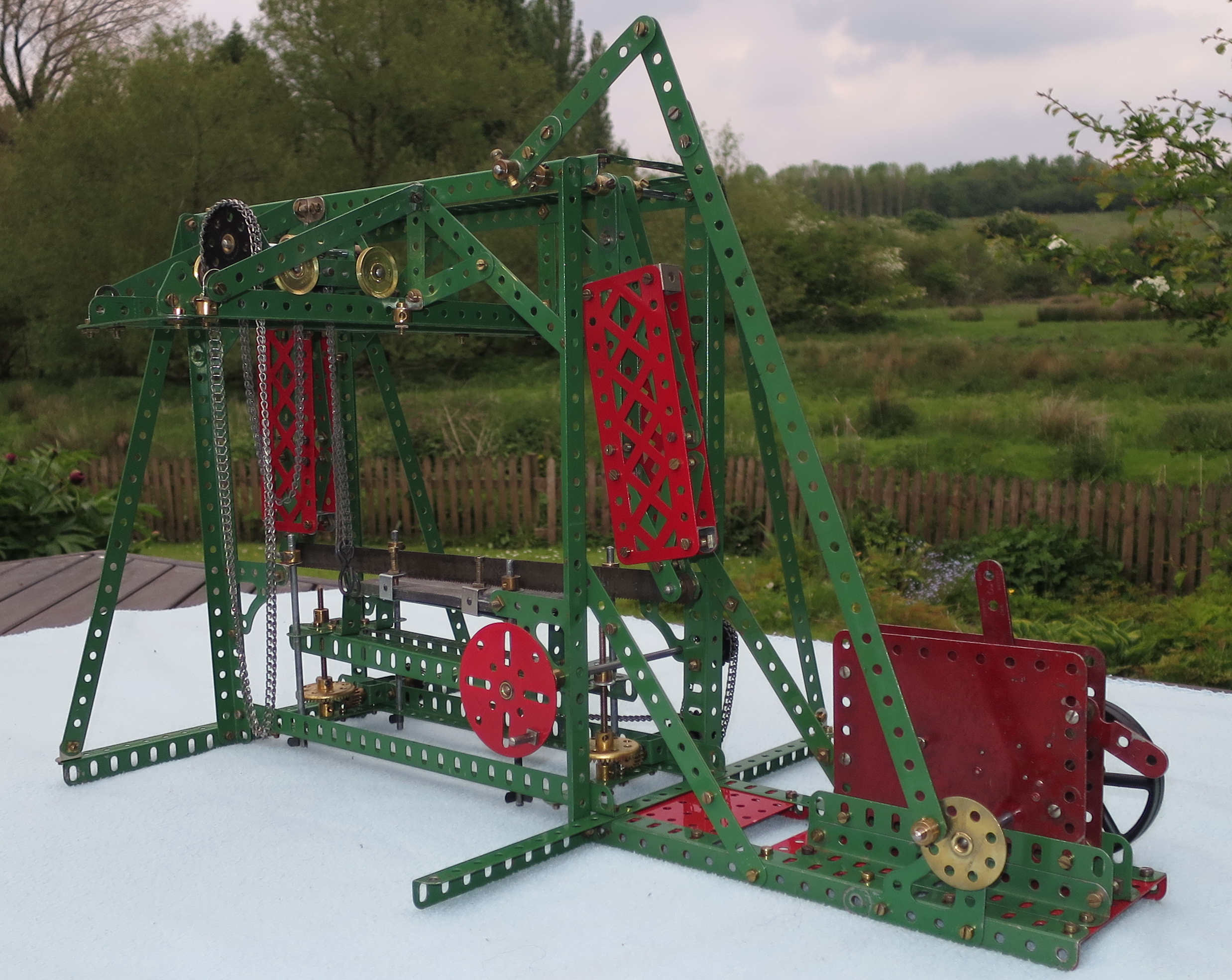
This is Super Model number 12, which I completed in early May 2026 after dismantling the Baltic Tank Loco. I couldn’t really build anything until I’d taken the loco to bits as it used so many of my parts, including all my nuts and bolts. My trusty parts spreadsheet told me I had enough parts to be able to build four of the smaller Super Models, so my plan is to build all four over the summer and take them to meets in the autumn. The stone saw is the first of these, and probably the most interesting – to me anyway. As far as I know, it made its first appearance in the 1916 Meccano Instruction Book 1.
First impressions
This is the first model I’ve built using a 1930s clockwork motor, and I was sceptical as to whether it would actually be able to saw through stone. Nevertheless I was going to try. But first I wanted to build the model as illustrated in the leaflet (see photo above). This uses rack strips to represent the saw blade, so clearly can’t actually saw anything.
So I gathered the parts together on a tray, as I generally do. As usual the parts list in the leaflet left something to be desired. It called for 12 of part number 7, which are of course 24.5″ angle girders. It doesn’t need any 24.5″ angle girders, and that should read 12 of part number 8, i.e. 12.5″ angle girders. Not a good start. It turned out that there are also a few things missing altogether from the parts list:
4 more 2.5″ strips (part 5)
4 more angle brackets (part 12)
8 x 0.5″ bolts (part 111a, to mount collars)
4 x 1″ sprockets (part 96)
Additionally, the list of rods given aren’t the best lengths for the job, and I’d guess they were constrained by the statement on the front of the leaflet: “a No. 6 Outfit Model”. Oh, and it turns out the model doesn’t really use a 2.5″ x 1.5″ double angle strip (part 47) or 3 of the 5 2.5″ x 1.5″ double angle strips (part 48a).
The initial build
The build was mostly straightforward, as it’s not a very complex model. The main problem I hit was in building the gantry rails – the track for the overhead trolley to run on. What’s not made clear in the text or the photos is that the gantry rails are not central in the model. They are halfway between the two ends of the saw, but the middle point of the rails is not over the saw. The 5.5″ strips (77 in fig. 2) are only at the front of the model, i.e. above the work table wheel. They bolt to the penultimate holes of the gantry rail 12.5″ girders (24 in figs. 1 and 2), not the third holes from the end, despite what figs. 1 and 2 seem to show. And the equivalent strips to 77 at the back are 3.5″ strips, bolted to the end holes of the girders. All that took a fair bit of working out.
The motor moved the saw, and I was reasonably happy with the model, but it was clearly going to need more than just the addition of a hacksaw blade to get it sawing stone. And the eagle-eyed may notice that I’d mounted the table adjustment wheel in the wrong place.
The working version
To quote from the Super Model leaflet: ‘By substituting a hack saw blade for the Rack Strips that represent the saw, the model may be used for practical purposes.’
To get this model ready for an attempt to saw through rock, it needed toughening up. I was lucky enough to have an old hacksaw blade with holes 30cm apart that were a good fit for a Meccano rod, so that bit was easy. I already knew that a hacksaw blade would cut through slate, so I broke up a broken roofing slate to give me something the right size to saw. Here are the fixes I made to get it more or less working properly:
The swinging frames were nowhere near rigid enough, giving a lot of lateral movement. To resolve this I added 3 more cranks to the top of the frames so each side of each frame was more rigidly attached to its rod. I also doubled up the set screws on the cranks on the right-hand side (rod 4, fig. 1).
The blade wobbled. I fixed this by sandwiching the blade between two collars at each end.
The motor was struggling to saw anything – it stopped as soon as the saw hit stone. I needed to improve the power getting through to the saw:
I extended the 12.5″ strip 6 (fig. 1) by 1.5″ using a 2.5″ strip. This gave better leverage.
I replaced 5″ rod 4 (fig. 1) with a 5.5″ rod, which allowed me to double up crank 5. With 2 set screws for each crank it stopped slipping on the rod.
I added a flywheel to give smoother running, which made a big difference. To do this I raised the motor up 0.5″ using 5.5″ flat girders, replacing the flat trunnion with a corner gusset. This was necessary to get the flywheel off the floor. I replaced the motor rod with a longer one (5″) and mounted the flywheel on the end. I could have added another corner gusset, but it would have added friction, so I didn’t.
The work table needed a bit more flexibility, and I needed to prevent the blade coming into contact with the screwed rods. I raised the work table by 0.5″ by replacing the four 0.5″ reversed angle brackets (part 124) with 1″ reversed angle brackets (part 125). I moved the four corner gussets up one hole, and replaced the four 4.5″ guide rods with 5″ rods.
The screwed rods kept jamming at their base, preventing the table from moving up and down smoothly. The threads were catching on the strips. I fixed this by replacing the two double bent strips with double arm cranks.
To hold the slate in place I made two simple clamps from 0.5″ double brackets, 0.75″ bolts and a couple of nuts. My guess is that the prototype wouldn’t need clamps due to the weight of the stone being sawn, but some things don’t scale!
…and after all this the saw just about cuts through slate. Very slowly! More photos:
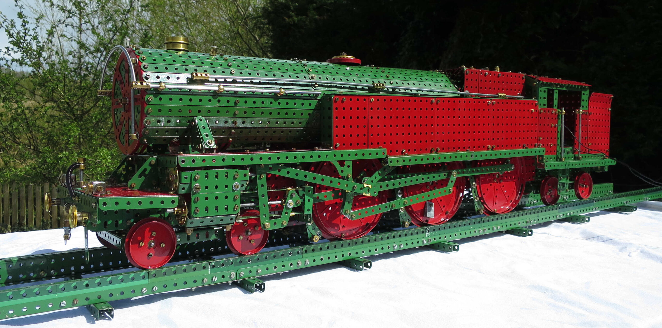
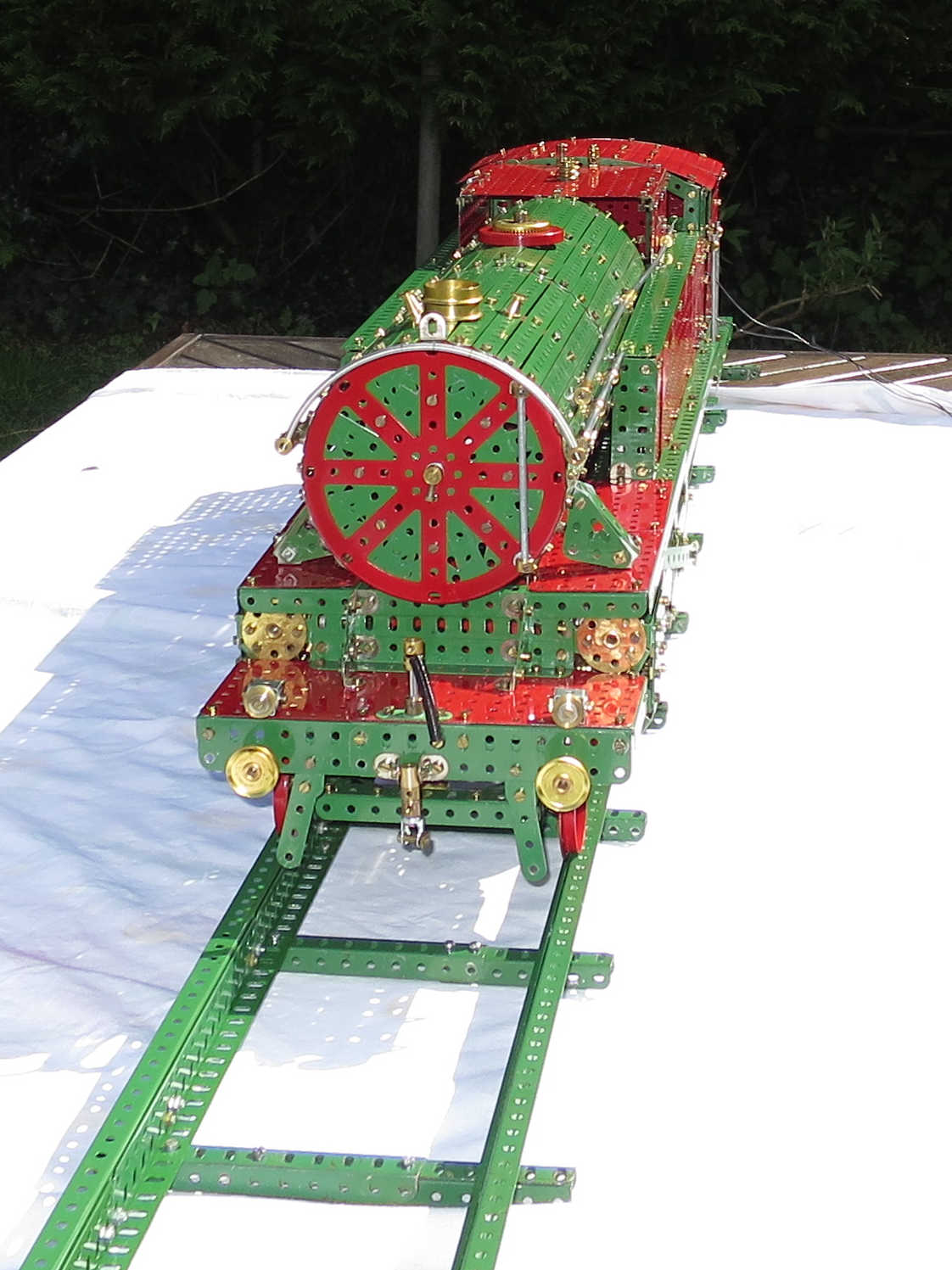
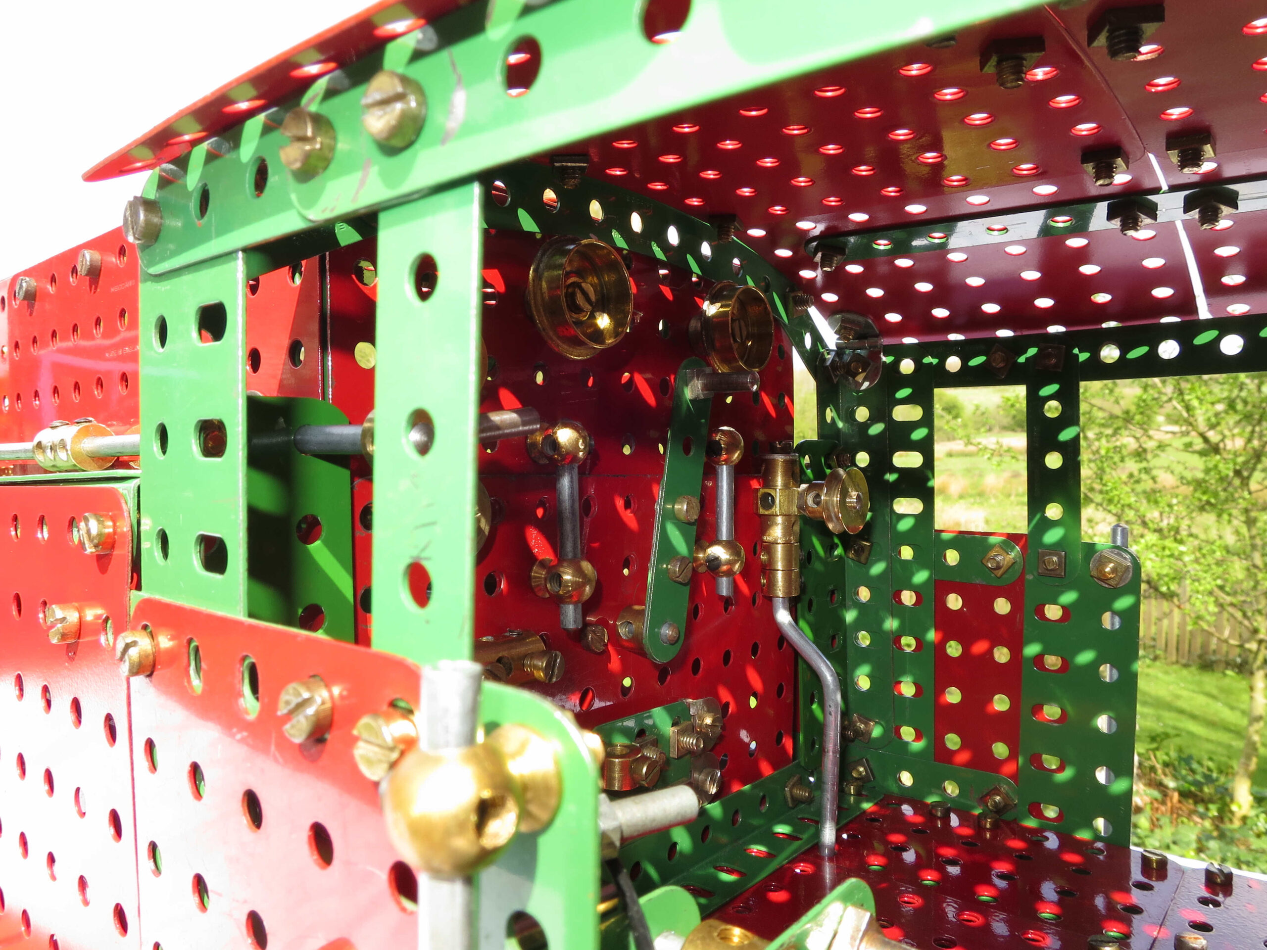
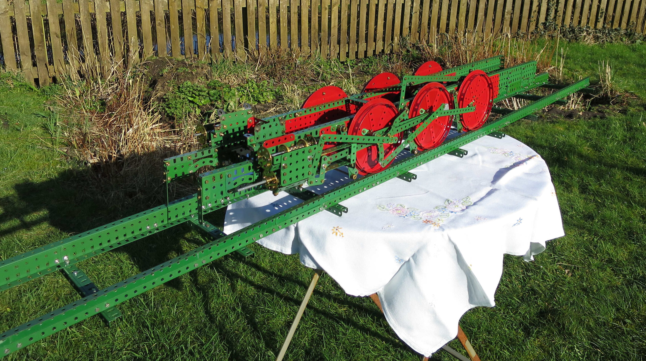
I completed this model at the end of March 2026, and took it to the Oxton meet on 25 April. It was big, nearly 4 ft long, and I had to buy more nuts and bolts to complete it. It looks great, and was fun to build. As far as practical I was faithful to the design instructions and illustrations in the 1928 Super Model leaflet as reproduced in Geoff Wright’s book.
As usual, the parts list was inaccurate in places, the instructions didn’t always match the pictures, and the pictures contradicted each other occasionally. All par for the course. One or two things in the instructions were clearly incorrect as well.
But, all the issues were pretty easy to resolve, and it’s a really good one to build. It’s one of the most visually attractive of the Super Models as shown in the leaflets (in my view), and that’s why it was high on my ‘must build’ list. The only snag holding me up was that to be faithful to the original I needed two 25 gramme weights (part no. 67), obsolete since 1940, and quite difficult to get hold of. Luckily a casual query from me resulted in John and Marie finding me a couple of original parts, for which I was very grateful.
Main build issues
I had to bend quite a few strips and plates, and respray quite a few old plates too. I already had a strip bender, but I had to invest in a longer set of rollers to bend the plates. I can recommend John Thorpe‘s rollers.
I don’t have the 4-volt motor used in the original model, and used a post-war E20R motor instead. This has a shorter frame than the pre-war 4-volt motor, so I needed to extend the frame with a couple of flat trunnions to hold the 2.5″ rod that carries 57-tooth gear 24. In the original model this rod also carries a 0.75″ pinion that engages with the 3.5″ gear on the axle for the middle driving wheels. This was trying to move the model too fast for my liking – I only had 6ft of track – so instead I journalled an additional rod in the main frames 2″ in front of the said axle. Instead of the 0.75″ pinion on the trunnion rod I fitted a 0.75″ sprocket, which drove 2″ sprocket on the additional rod. This rod also carried a 0.5″ pinion that drives the 3.5″ gear. This resulted in a speed reduction of about 3.4 times, which gave a more appropriate speed along the track.
I was worried that the motor wouldn’t be capable of propelling the model, which weight about 25lbs. I was pleasantly surprised. Once I’d got everything lined up properly, oiled and greased appropriately, and fixed a design issue (described below), it worked very well. I doubled up all the set screws and grub screws on the main drive train, and bolted a 1.5″ pulley to the 3.5″ gear to give it 4 set screws in total.
I modified the motor control lever slightly by extending the crank 96 with a 2 1/2″ strip. A 4″ made-up strip (as in the leaflet) connected to the left-hand motor switch tag worked a treat.
The model needs 10 x 5.5″ flat girders, not 8 as given in the part list. Similarly it needs 9 x 2″ strips rather than 7, and 11 x 1″ rods rather than 7. Luckily I had them.
The model as designed won’t run on rails, only on a flat surface. The bogie wheel flanges are 1/4″ smaller than those on the driving wheels, and when you put the model on rails this lifts the bogies higher and the bogie frames foul the main frames. To fix this I took the 7.5″ flat girders off the bogie frames and turned the 7.5″ angle girders round so I could journal the axles in the long holes of the girders.
The model still wouldn’t run on the rails shown in fig. 1 of the leaflet. The bolts securing the rails foul the driving wheel flanges. If you want it to really run on rails (as I did) then the rails need redesigning. I bolted two rows of flat girders onto the angle girders of the original rails, loosely bolted, wedged another row of angle girders between the flat girders, then tightened up the bolts until the angle girders were secure. I could probably have found a simpler solution, but this worked.
The weigh shaft (see leaflet page 4 para 2) is specified as a 6.5″ rod, and this was too short. The 3.5″ strip 58 and its crank fouled coupling rods 48a and 49, with no obvious way of adjusting it. By using a built up 7.5″ rod instead, the 3.5″ strip and crank were now outside the coupling rods, and the problem went away.
The side handrails on the boiler are described as 8″ rods, but the illustrations clearly show 10″ rods, i.e. non-standard parts. I resolved this by extending the rods to 10″ with straight rod connectors and 2″ rods.
The lamps can’t be built as described (page 5 para 4 of the leaflet), as far as I can see. The eye piece and double brackets can’t be bolted together like that, or at least I can’t do it. Instead of the eye piece I used a pair of angle brackets outside the double brackets to form the clip. I put a 0.75″ bolt through the long hole of one angle bracket, through one side of the double brackets, through the axle hole of a collar, then through the other side of the double brackets and the other angle bracket. Add a nut, adjust the clip to fit neatly on a lamp iron (i.e. another angle bracket) and tighten the nut. Put a washer, a 0.5″ pulley without boss and another washer on a 3/8″ bolt and screw it into the collar and you’re done.
The front of the boiler isn’t shown in the leaflet. An earlier 4-6-2 version of the model appeared in Meccano Magazine, but it looks a bit ugly so I didn’t copy it. I just added a door handle centrally (a collar bolted to the central hole with another bolt in it for a handle), and a 3.5″ rod mounted vertically on collars on the RHS to represent the hinge.
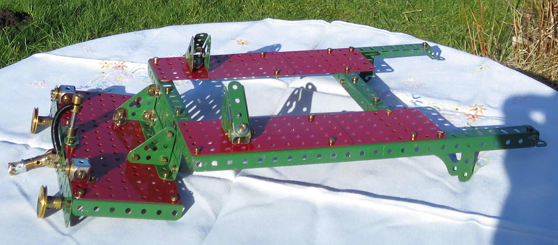
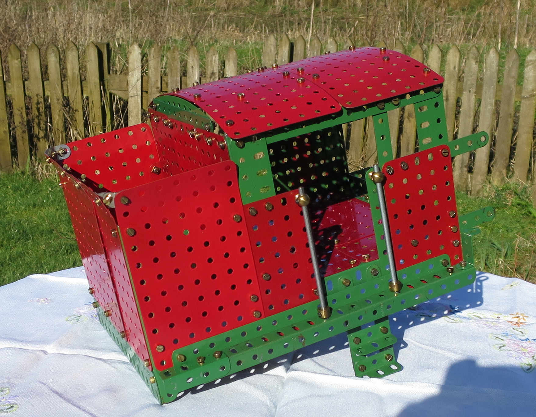
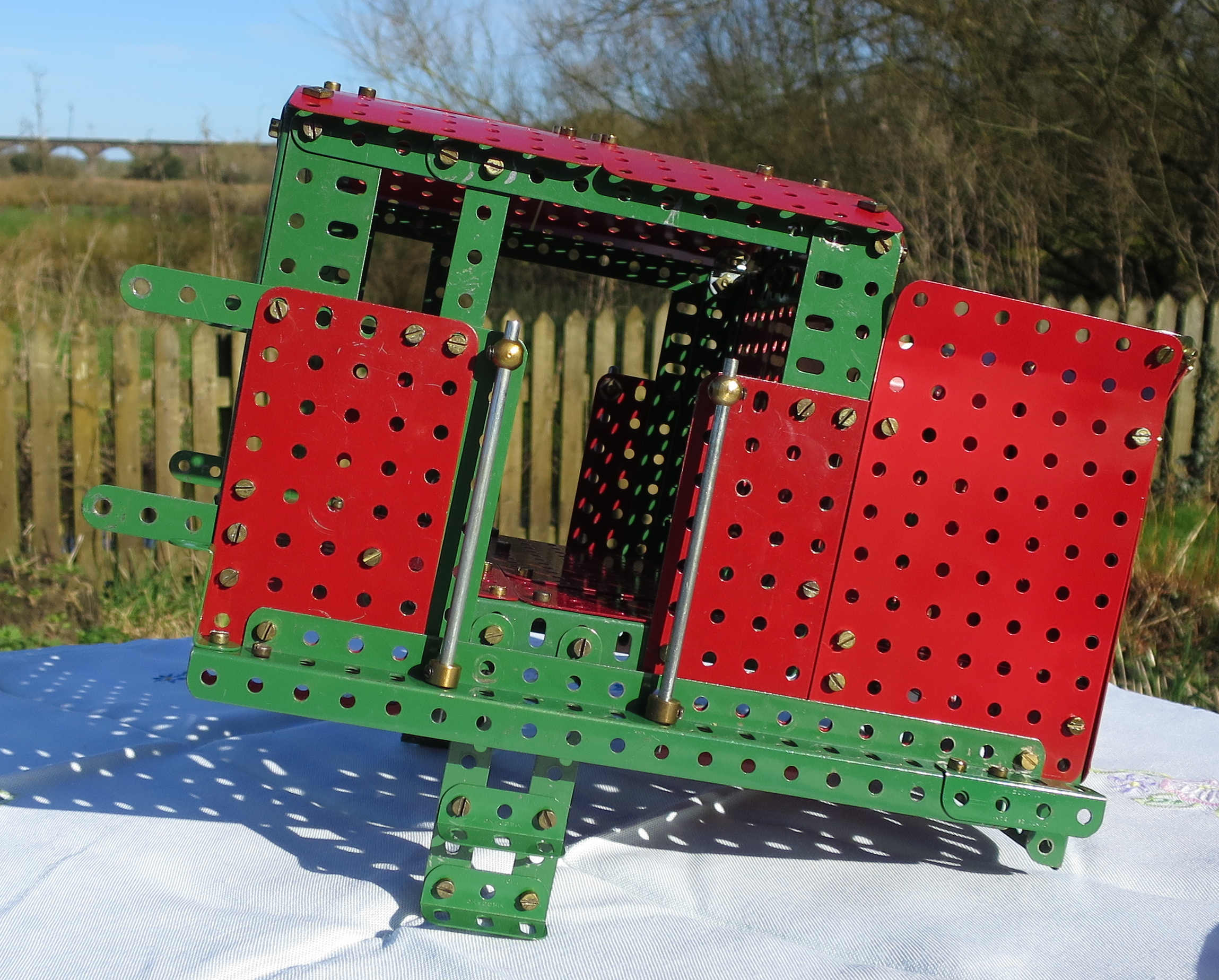
The photos below show some of the main units of the build as I was going along.
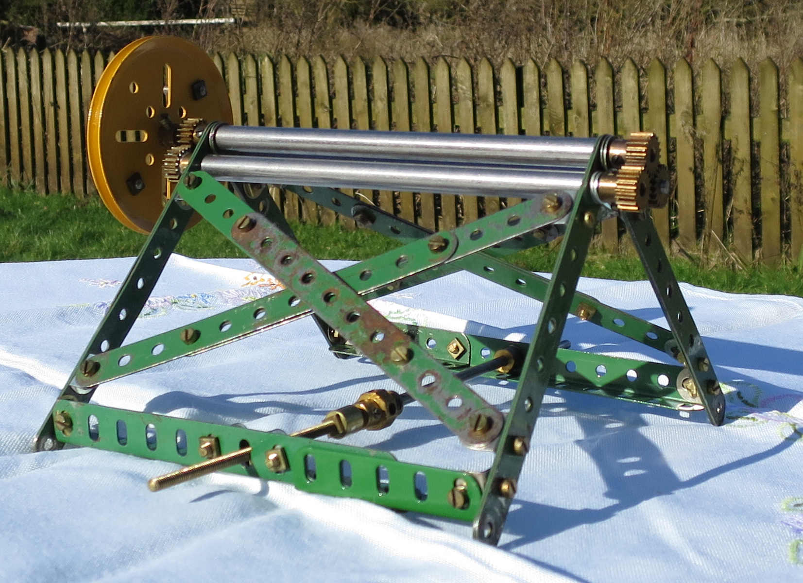
I’d already built a strip roller, but the rollers on that are only 3″ long. To build the Super Model no. 15, the Baltic Tank Locomotive, I was going to need a roller capable of bending plates 3 1/2″ wide. To be honest I wasn’t sure whether that could be done with Meccano, as it needs a lot of pressure to bend those plates. I decided to have a go anyway, although I had a fallback plan to use flexible plates instead if I couldn’t bend the rigid plates.
The 6″ rollers once more came from John Thorpe, and the roller was based on the design of my strip roller. I made this one a bit stronger, replacing the transverse strips with angle girders.
The roller works pretty well, considering it’s such a simple construction. I needed to bend two sets of 5 1/2″ by 3 1/2″ plates for the loco model. The first set was for the cab roof, and needed a fairly gentle bend across the whole plate. By very gradually increasing the bend in repeated rolls, I got a very good curve on the plates, and the roller didn’t explode. The second set of plates was for the top of the coal bunker, which needed a tighter curve, only at the end of the plates. Getting this tight curve was too much for the rolling machine – I just couldn’t roll the plate through the machine. What I could do though was to bend the plate without rolling it, then move it on a bit, then bend a bit more. That worked well enough to get the bends I needed.
I’d just add that the rollers themselves didn’t bend at all under the pressure. It was just too much for my Meccano. Thanks John!
As for bending an 8″ axle rod into a semicircle, which the loco also needed, I did that using a Workmate, a length of pipe and a pipe wrench!
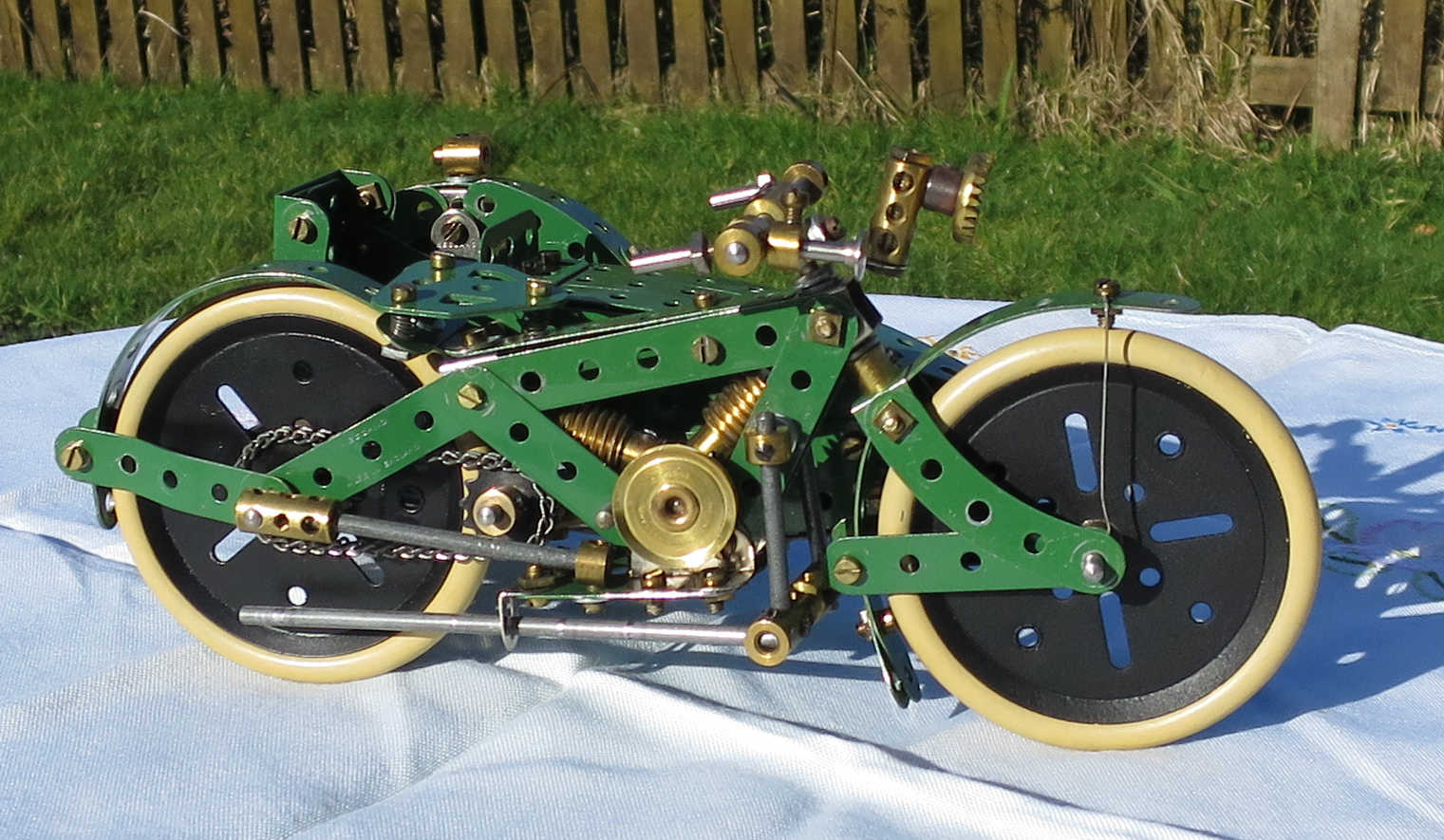
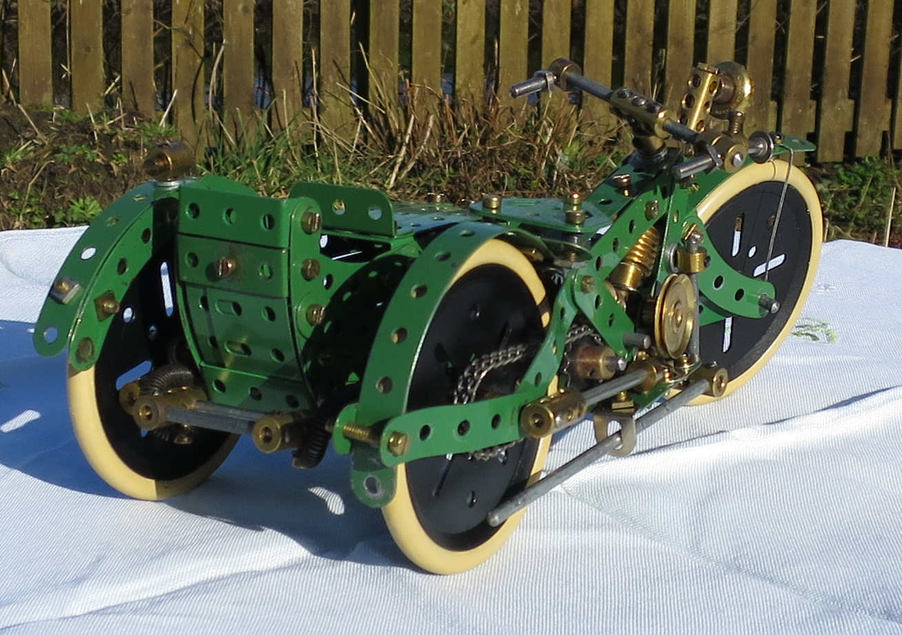
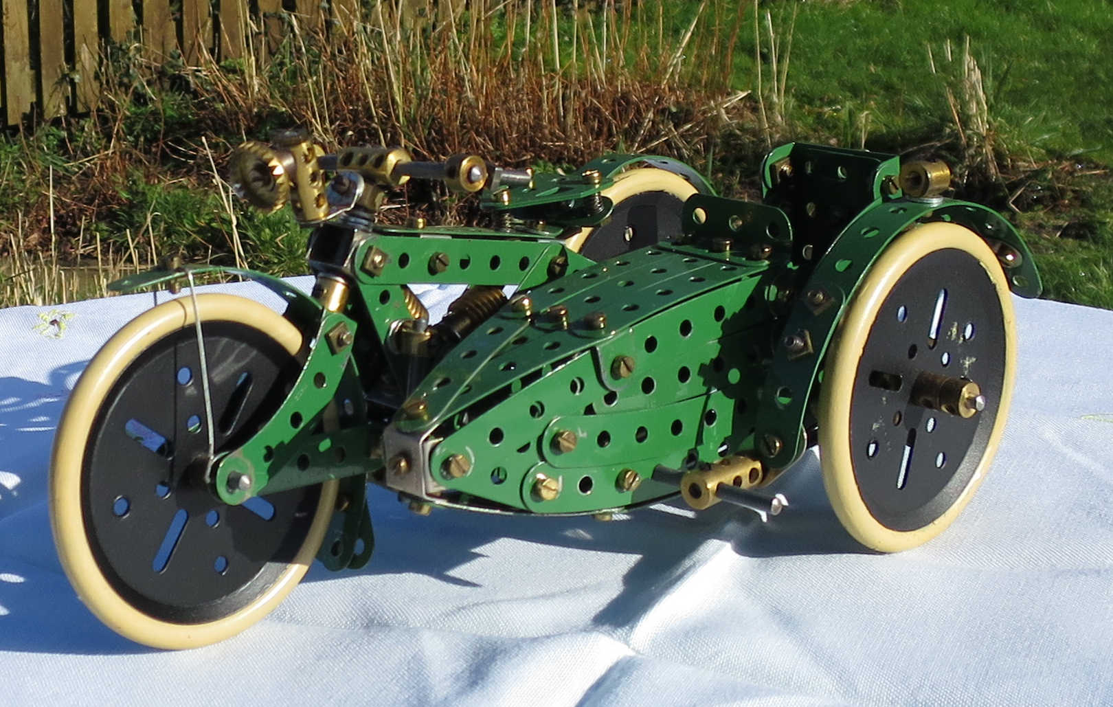
This is the smallest of the Meccano Super Models (number 3 in the series), and in my view it’s a very elegant representation of a 1920s motorbike.
This model featured in Meccano Magazine in January 1926, and the leaflet for the model was first published in 1928. There are some fiddly aspects in the build – smaller fingers would have helped! The original tyres (part 142) are virtually unobtainable, and this model uses modern recreations based on the original Meccano blueprint. To build this model with the usual post-war 3″ tyres (part 142b) would require some redesign, as they would be too bulky to fit.
The leaflet for this model was included in the 1928 to 1934 Outfits 6 and 7, and it was withdrawn in 1935.
The build
This one was a joy to build. It needs some judicious bending of strips and the flat girder that forms the back of the sidecar, and I’d recommend the use of a strip roller for this. My build follows the leaflet faithfully, apart from a slight improvement in the mounting of the headlamp – I’ve used a 1″ threaded rod in the coupling 53 rather than relying on the poorly secured 3/4″ bolt suggested in the leaflet.
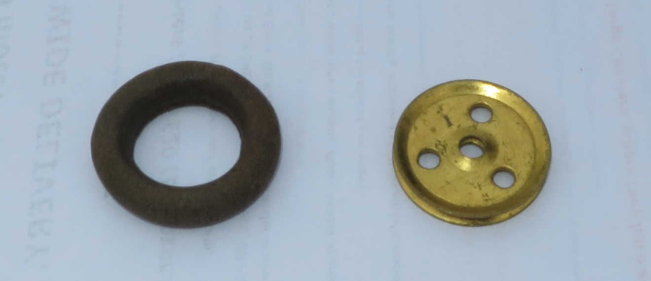
In the 1929 No. 7 outfit there was a single squashy rubber ring included, with part number 155. It appears to have been intended solely for building the clutch mechanism for Super Model 1 – the New Meccano Motor Chassis. The 5/8″ is a bit misleading, as the external diameter was greater than this, but it’s not the same part as the thinner and harder 1″ ring introduced in 1937 for use as a tyre on a 1″ pulley. The latter part was initially numbered 155a, but was renumbered 155 later, once the original 155 had disappeared from the catalogues and outfits.
If you’re building the Super Models, you need to know that it’s this old part you should be using: 1 for either version of the Motor Chassis (1 and 1a), and 2 for the New Loom (16a). However, as far as I can see, it’s probably only the later version of the Motor Chassis (1a) that really needs it. In the earlier Motor Chassis, the ring is fitted over a 1″ pulley, so a later 155 ring would probably do the job (I haven’t built this clutch so can’t be absolutely sure). The later model uses the ring as a loose fit over a 1/2″ pulley, pushing it against a 7/8″ bevel gear for friction, so the later 155 ring won’t do the job – you’d have to do a bit of redesign. As far as the loom is concerned, the later part 155 works fine.
I thought I didn’t have any of these, but I just thought I’d check through a box of what I thought were non-Meccano bits that were in a box of assorted parts I bought alongside my No. 10 outfit. Lo and behold I appear to have one. It’s old and a bit perished, but it ought to survive being built into a Motor Chassis 1a clutch at some future date. The photo shows it next to a 1″ pulley for scale.
These were the very first Meccano tyres. Their first appearance looks to have been in a revised version of the Meccano Motor Chassis leaflet in 1921: the tyres in the illustrations look identical to part 142, but no such Meccano part had been announced at this point. These leaflets predate the main Super Model series, and the model is not the same as the later Super Model no. 1. The same 1921 chassis and tyres featured in Meccano Magazine, in the September and October 1923 issues, and again in the February 1924 issue, which featured a limousine body based on the same chassis. Two months later there was a tiny announcement printed in the April 1924 MM issue that finally mentioned that part 142 was available. They also appeared listed in the available parts in the 1924 Meccano manual.
These rings pre-date the better-known 3″ tyres by about four years. There were 4 in the largest 1926 outfit (No. 7), but in 1928 the Dunlop tyres effectively replaced them. Three rings were retained in the No.7 outfit and its successor L outfit though, so that you could build Super Model no.3: Motor-cycle and Sidecar. When the new No. 10 outfit appeared in 1937 they were gone, and they never reappeared after the war. I imagine they were retained purely because the new tyres were too bulky for the design of Super Model 3. The blueprint diagram shows they were 3 1/8″ external diameter, 2 1/2″ internal diameter, made of circular cross-section vulcanised rubber with a diameter of 5/16″. They were either white or off-white.
I wanted to build the motor-cycle model so I needed three of these rings. Originals are next to impossible to find, so I looked around to source something similar. Luckily there were Nitrile Rubber O-rings the same size available on Amazon, although they are black. They cost a bit as they are shipped from China, but they are the right size. The ones I’d recommend are 85mm x 69mm x 8mm. I bought one with 80mm external diameter first, but it was difficult to get onto a 3″ pulley. The 85mm rings are a good secure fit. Next I painted them with three coats of Humbrol matt cream acrylic paint. I went for cream rather than white as old rubber is not going to be white for long, and cream seemed more appropriate for a vintage look with red/green Meccano. They look good. Stretching them onto pulleys resulted in a little damage, but that touched up pretty well, and they aren’t coming off again as I’ve got plenty of pulleys.
I’m now planning to build the Meccano Limousine featured in MM in February 1924, so I’ve ordered a fourth O-ring. Watch this space – it’s probably going to be my project for Spring 2027.
…which is a bit of a mouthful. I think it probably means a table for machines that produce designs, i.e. patterns. And not a table that designs machines. That would require a lot more AI than Meccano could deliver..
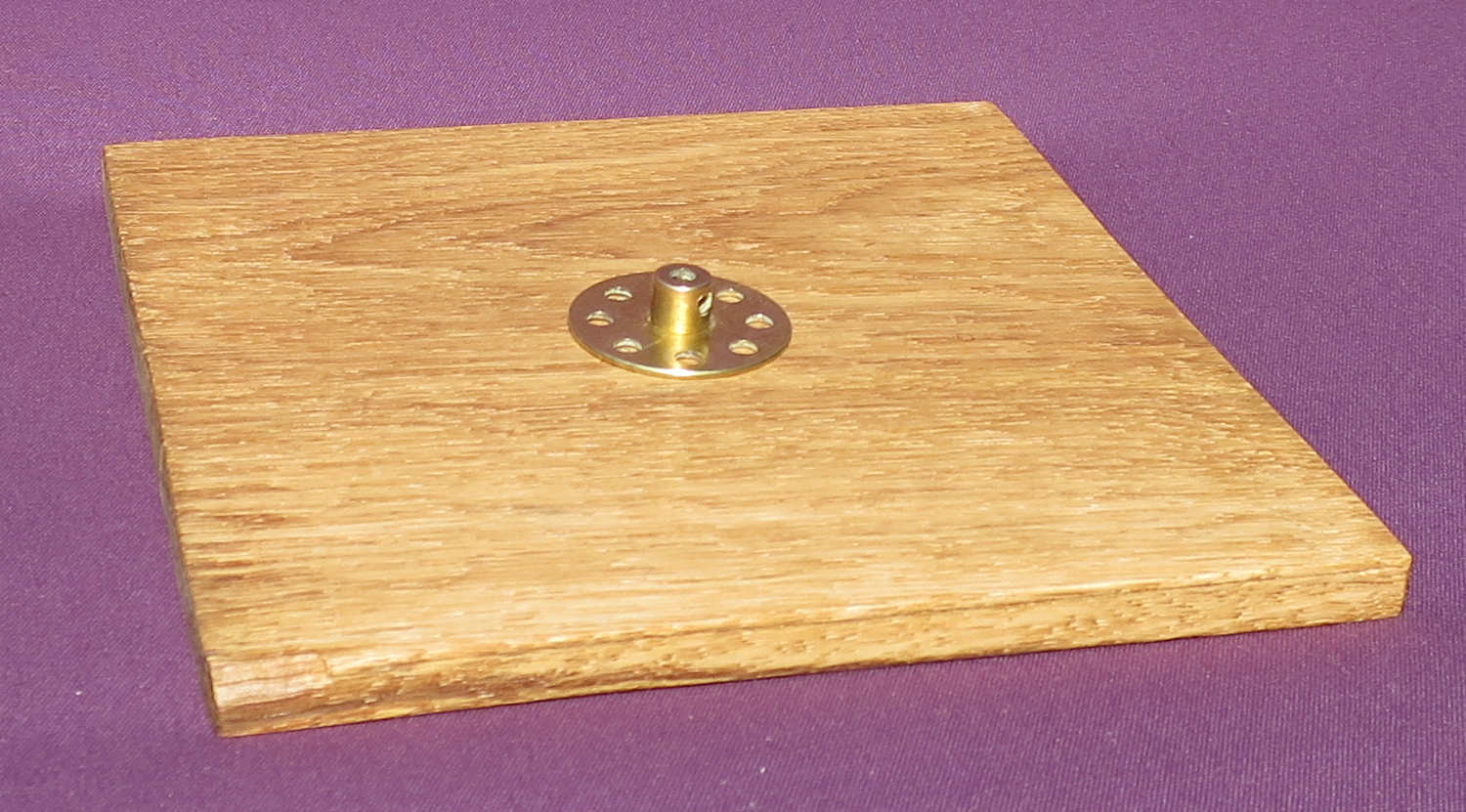
This is one of those parts that is pretty much unavailable anywhere, but that doesn’t really matter, as it’s easy enough to make one with basic woodworking skills. And you’ll need one if you want to make one or both of two of the pre-war Super Models: the Meccanograph (no. 13) and the Harmonograph (no.26). Part 107 first appeared in about 1921, was included in the biggest outfits (7 then L) from 1922 until 1936, was not in the 1937 outfit 10, then never reappeared post-war.
To make one you need a piece of hardwood 6 1/2″ by 6 1/2″ by 5/16″. I made mine from an off-cut of an oak floorboard I had lying around in the garage. I had to plane it down a bit to reduce the thickness. It needs a smooth flat finish. Sand it smooth, stain it if you wish, then oil or wax it with a furniture polish. Screw a bush wheel (part 24) to the centre of the underside of the board with 3 or 4 black round-headed screws. 3/8″ no. 6 screws are about right – just make sure they’re not going to stick out of the top of the board. I made my board 3/8″ thick to be on the safe side. Hardwood really needs 1/16″ guide holes drilling before the screws go in – again be careful not to drill all the way through the wood, practising beforehand if you’ve not done this before. I tape up the drill with electrical insulation tape to mark the right depth. You’ll probably notice there are no screws in mine in the photo – I was waiting for Amazon to deliver the screws!