Updated March 2026

Intro
The first Meccano loom I can find information about was a competition winner in 1914. A different loom model shared first prize in the 1915/16 competition, and this appears to have been the original model from which the Super Model looms derive. I built the revised Super Model version.
The gathering of the parts
In the early summer of 2024. I plucked up the courage to have a go at building the second version of the Super Model Loom. I’d been collecting parts for a while: as well as an inordinate number of 2 1/2 inch strips it also requires some special parts that haven’t been made by Meccano since WWII, and they probably never made very many in the first place:
- A shuttle (part 104). You have to have a Meccano shuttle, or a reproduction of one (brass ones do exist). I was lucky enough to get hold of a 1930s original, looking identical to the one in the Super Model leaflet. It has squared ends to the apertures, rather than the rounded ends I’ve seen in some photos.
- A reed hook (part 105). This is not strictly speaking part of the model, but you need one to operate the loom. Meccano reed hooks are like hen’s teeth, but I found what looks to be a similar reed hook here. It did the job perfectly well.
- A sand roller (part 106a). Again, you rarely see an original on sale. They are similar to the wood rollers (part 106), but the wood is of slightly larger diameter, and is covered with a perforated thin steel sheet like a fine cheese grater. It’s job is to grip the finished cloth as it comes off the loom, enabling it to be wound onto a wood roller. I made my own, using a wood roller. I wound a strip of paper onto the roller to give it the added diameter. I bought some steel sheet (from here), cut it to size, and perforated it with a fine masonry pin (as used for picture hanging). Hundreds and hundreds of times. Then I nailed it to the roller. It looks the part, and it does the job. By the way, the original Binns Road parts never had sand on them, although apparently Meccano Spain stuck sandpaper round some wood rollers at some point and sold them.
Some photos of these parts:


The hiatus
In July of 2024 I was all ready to tackle building the loom, but I had a serious accident, and for a year I was unable to wield a screwdriver. It was only in the summer of 2025 that I was able to get working seriously on this project. I could still only work at it for a couple of hours a day maximum before things get a bit painful. But to be honest, building this loom was so challenging that a couple of hours a day would be enough anyway…
The loom build
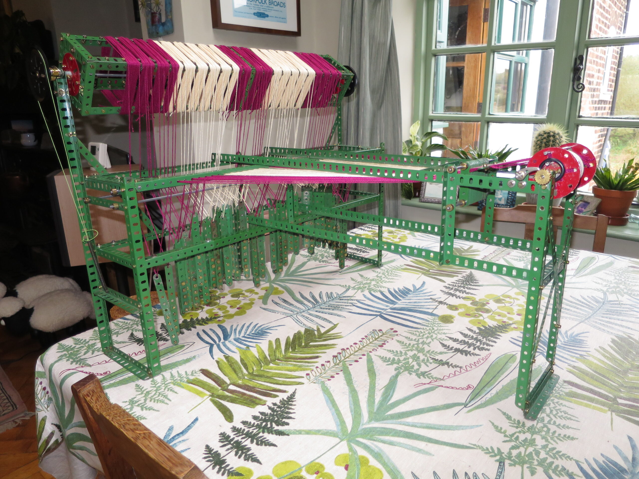
The build went OK really, and eventually the whole loom appeared to be working properly, once I’d lubricated everything and done a fair amount of adjusting. That’s without any yarn though. The picking motion ended up being pretty impressive, flinging the shuttle across pretty quickly, although not completely reliably. The healds look a bit of a mess – the pictures in the leaflet show the healds all neatly parallel, and mine certainly aren’t, but then the leaflet photo was probably doctored anyway, as most of them are.
The instructions aren’t bad really, in that I didn’t find any major mistakes in them. Lack of clarity all over the place of course. As always I had to make some changes to the build where things didn’t work as described, and had to improvise and guess where the info in the text and pictures wasn’t clear enough. Here are the main things I’ve had to fix so far:
- The power through the rods needed to drive the complex set of movements is too much for the bolts and grub screws to hold on to the rods. I knew this would happen as the instructions warn you about it. It wasn’t enough just to double up on the screws though. I also put a second bush wheel on the circular plate acting as the crank, fastened each cam to its neighbouring gear wheel using a socket coupling, and doubled up the 4 cranks at the top of the loom that drive the picking motion.
- As far as I can see from the leaflet, the spring cord forming part of the picking motion is attached by magic and little else. I used couplings and bolts to attach it to the picking sticks, and spring cord hooks to attach it to the double bent strips.
- It’s clear from Figure 1 in the leaflet that the flat trunnion 10 holding the rod suspending the heald frames is mounted centrally on the top girder 5. But this means the heald frames don’t hang centrally. Moving the flat trunnion one hole leftwards fixes this.
- The tension springs holding the heald frames down are expanded far too much if they are attached to hooks on the bottom girders 20. Instead I raised the attachment point 2″ by attaching flat trunnions and 2 1/2″ strips to the girders 20.
- The tips on page 7 of the leaflet about adding a 2″ flat girder to the cam and doubling up on the springs made a big difference to the picking stick action. I’d recommend them.
More pictures:


The Beaming Frame
The beaming frame was an easy build. There’s a half-inch discrepancy in the retouched Figure 9 in the leaflet – the girders joining the take-up beam to the rest of the frame aren’t level. This is an easy fix though. The long rods that the threads go round on their journey from spool to beam needed some support in my view, so I added strips halfway across to journal them. And it’s important to make the reed on the beaming frame the same width as the wood roller you’re winding on to, so after my first attempt I added more washers to the reed. The first time I tried it I didn’t get the yarn wound evenly across the beam, which messed up the tension.
Loading the yarn onto the beaming frame takes forever. I did this three times in all. Both on the beaming frame and when transferring the yarn to the loom I made us of a number of simple clamps to keep groups of threads from tangling. These were pairs of 2 1/2″ strips bolted together at either end – like hair grips.
The beaming frame:
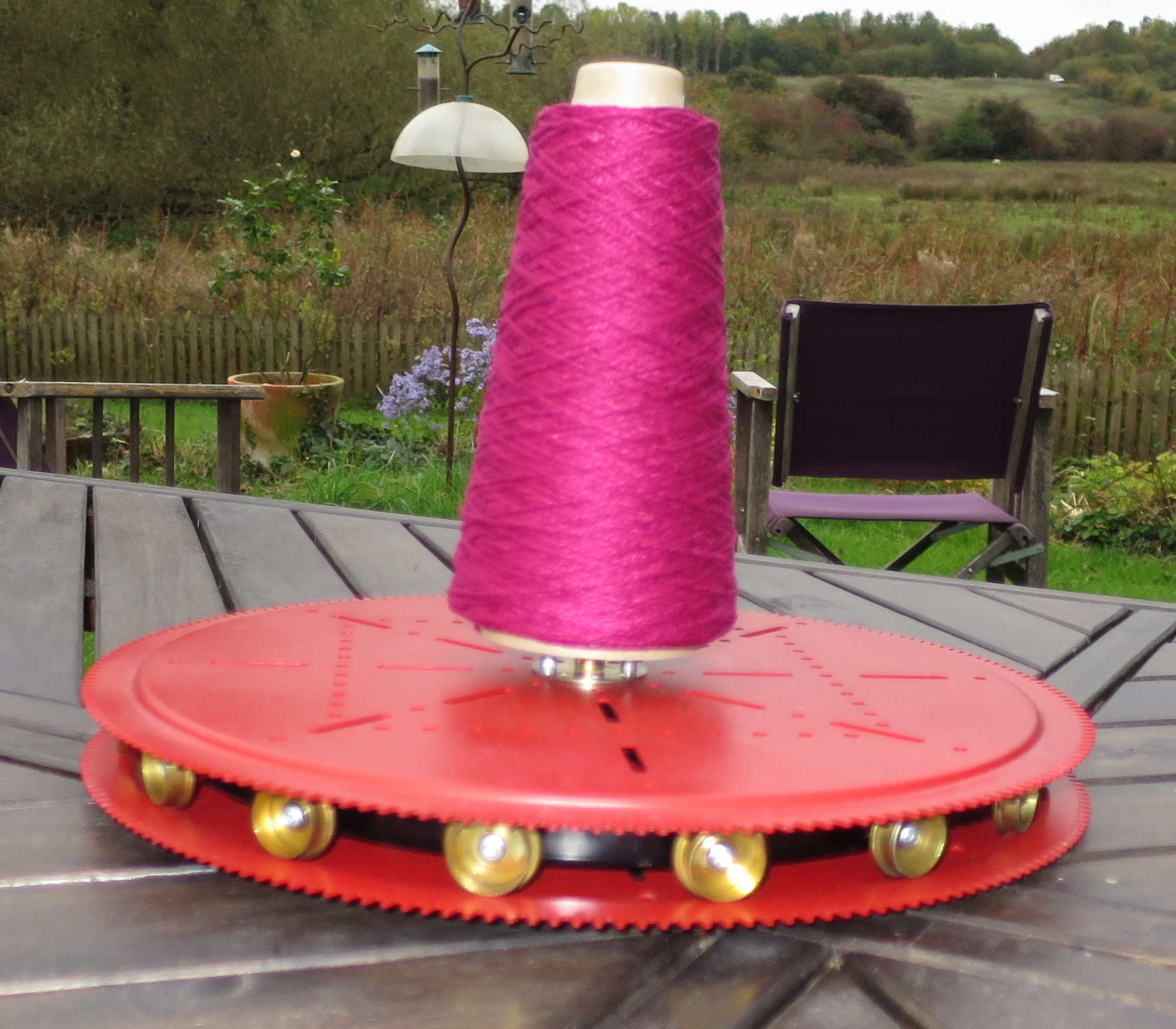
I needed an easy way to get the yarn off its spools and onto the beaming frame’s spool. I just put a rod into my geared roller bearing, put a loose road wheel on the rod, and fixed a 1″ wheel at the top of the rod. This meant my yarn could unwind from the original spool without me needing to touch it. My hands could then concentrate on winding onto the beaming frame spool.
Trying to get the loom working – or not
To cut a long story short, I never did succeed in getting this loom to weave anything. I tried until I was so sick of it I decided to dismantle it and get on with building something else. Without yarn it appeared to work properly. With yarn, I just couldn’t get it to throw the shuttle across. It kept getting stopped by the warp threads, which wouldn’t separate reliably. I tried finer warp yarn, which improved things, but not enough to weave. I tried increasing the heald frame separation distance by lengthening the strips holding the sprocket chain (point 45 on Figure 5 in the leaflet). This appeared to help a bit too, but again not enough. I’ve not idea how the ‘warp tensioning mechanism’ was supposed to work, as there’s no coherent explanation in the leaflet and no illustration of how to thread it.
I’ll probably come back to this and try building this again, but not before I’ve found someone who’s got one of these working and can advise me. The prime suspects (in my mind) are the suitability of the yarn I used, and the warp tensioning.