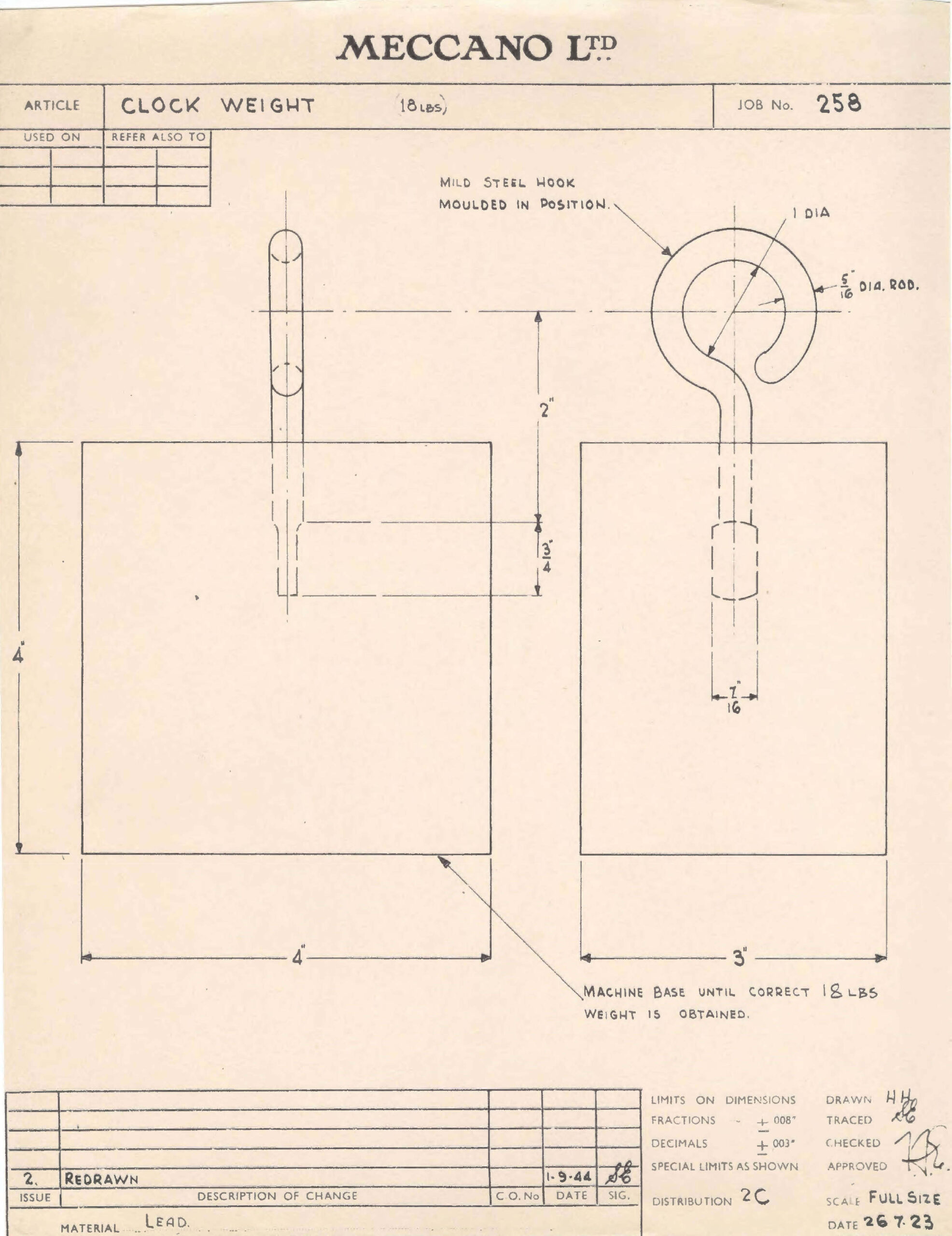
OK I’ll admit there never was a part 141a, as far as I know. There was a Meccano blueprint for a clock weight though, and we have a copy of the one that was redrawn in 1944, presumably from a 1923 original. It never made it as far as being an official Meccano part, and as far as I know none were ever made, although I’d be delighted to be corrected on that. You still needed an 18lb weight to complete either of the Super Model clocks though, and our plucky Meccano boys had to solve that one themselves. My betting is that very few built either clock. The Super Model 14 leaflet has a weight similar to this, but with the hook at 90 degrees to the blueprint, and the Super Model 14a leaflet appear to have a very different hook that might actually be a loop. Or artistic licence.
Anyway, it’s my ambition to make a weight according to the blueprint. I’ve no idea how I’m going to do it though. The hook should be feasible – all I need is a length of 8mm mild steel rod and a sympathetic blacksmith. It’s smelting and moulding the lead that’s the tricky bit. I’ve got the lead, but not the equipment or the expertise. Still, watch this space.
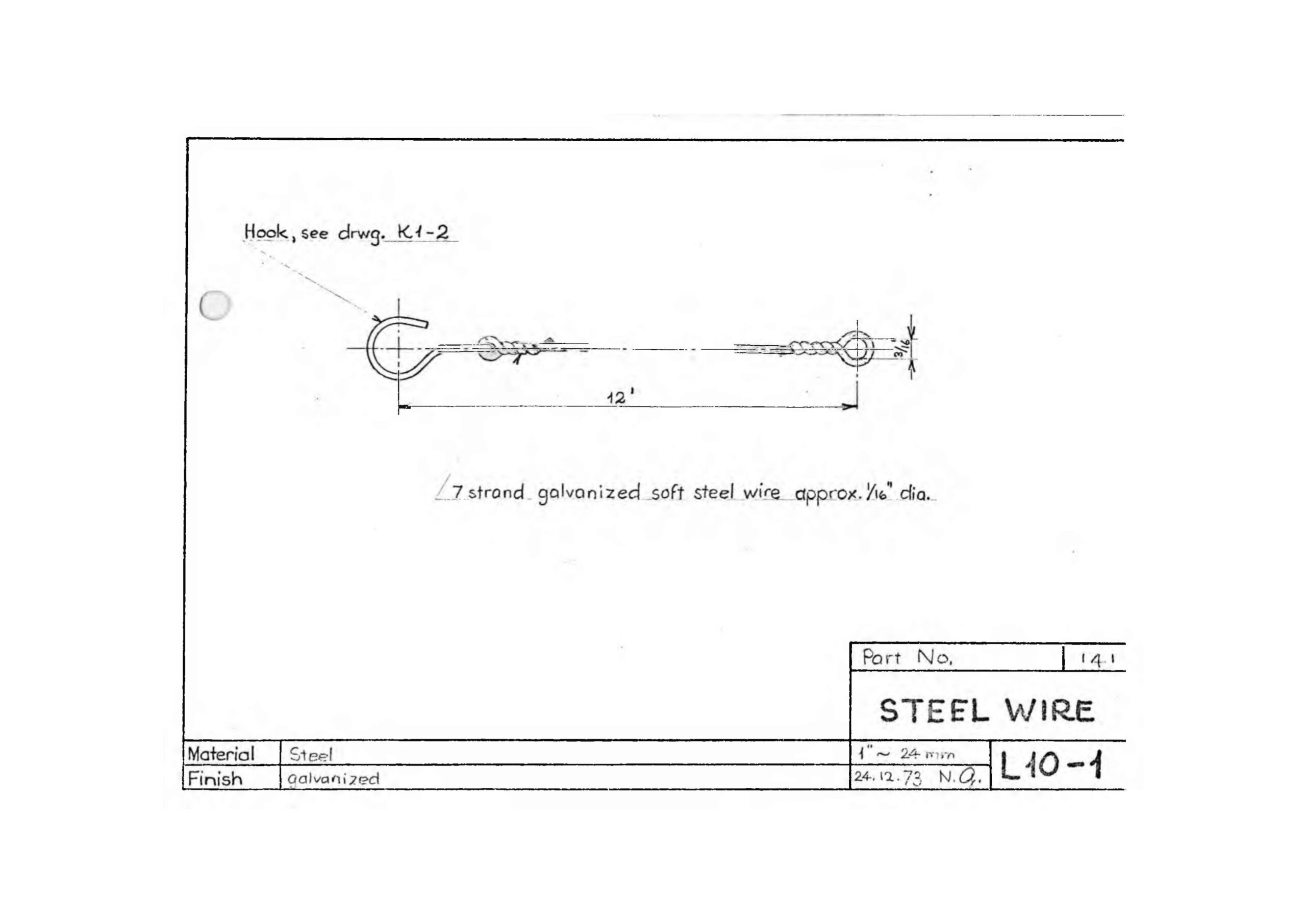
I’ve never even seen one of these, but if I’m ever going to build Super Model 14a, the Grandfather Clock, I’m going to need one. It seems to be reasonably easy to make one though, and there is a blueprint available online. It’s one drawn by Niels Gottlob in the 1960s or 1970s, not a Meccano original blueprint, but as far as I know it’s all we’ve got.
The hook is a normal pre-war Meccano hook, and the rest is wire that’s easy enough to find online, so I’m not too worried about recreating one of these. I’ve got the hook and the wire already.
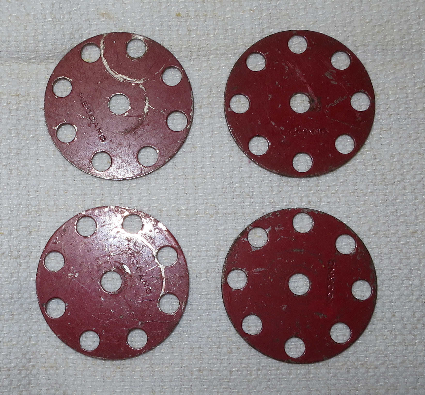
In 1932 Meccano launched the X Series outfits, which were a budget solution to Trix undercutting the main Meccano range. They weren’t particularly successful, and were discontinued in 1936. There were, however a couple of parts in the X Series range that were absorbed into the main Meccano range in 1937, as they filled in obvious gaps. One was the 3/4″ disc, which was renamed the 3/4″ washer and became part 217b, later renumbered part 38d. The other was X Series part X475, the 1 1/4″ disc, which became part 217a. It was red-painted steel, with eight holes. It was still in the Meccano parts list in November 1941, but that was the last we heard of it.
So there were two of part 217a in the Meccano Outfits 3 and 4, and four in the bigger outfits, for just four years. After the war, part 24a appeared in 1950, which was made of brass from the start, now the size of a bush wheel, i.e. 1 3/8″, and renamed the wheel disc.
I want to have an Outfit 10 ‘superset’ so I can build any Outfit 10 model from any era, so I needed four of these. And now I’ve got them.
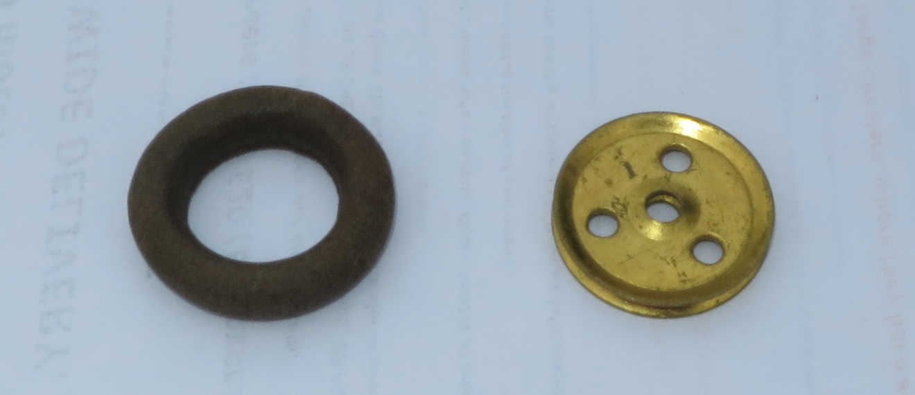
In the 1929 No. 7 outfit there was a single squashy rubber ring included, with part number 155. It appears to have been intended solely for building the clutch mechanism for Super Model 1 – the New Meccano Motor Chassis. The 5/8″ is a bit misleading, as the external diameter was greater than this, but it’s not the same part as the thinner and harder 1″ ring introduced in 1937 for use as a tyre on a 1″ pulley. The latter part was initially numbered 155a, but was renumbered 155 later, once the original 155 had disappeared from the catalogues and outfits.
If you’re building the Super Models, you need to know that it’s this old part you should be using: 1 for either version of the Motor Chassis (1 and 1a), and 2 for the New Loom (16a). However, as far as I can see, it’s probably only the later version of the Motor Chassis (1a) that really needs it. In the earlier Motor Chassis, the ring is fitted over a 1″ pulley, so a later 155 ring would probably do the job (I haven’t built this clutch so can’t be absolutely sure). The later model uses the ring as a loose fit over a 1/2″ pulley, pushing it against a 7/8″ bevel gear for friction, so the later 155 ring won’t do the job – you’d have to do a bit of redesign. As far as the loom is concerned, the later part 155 works fine.
I thought I didn’t have any of these, but I just thought I’d check through a box of what I thought were non-Meccano bits that were in a box of assorted parts I bought alongside my No. 10 outfit. Lo and behold I appear to have one. It’s old and a bit perished, but it ought to survive being built into a Motor Chassis 1a clutch at some future date. The photo shows it next to a 1″ pulley for scale.
These were the very first Meccano tyres. Their first appearance looks to have been in a revised version of the Meccano Motor Chassis leaflet in 1921: the tyres in the illustrations look identical to part 142, but no such Meccano part had been announced at this point. These leaflets predate the main Super Model series, and the model is not the same as the later Super Model no. 1. The same 1921 chassis and tyres featured in Meccano Magazine, in the September and October 1923 issues, and again in the February 1924 issue, which featured a limousine body based on the same chassis. Two months later there was a tiny announcement printed in the April 1924 MM issue that finally mentioned that part 142 was available. They also appeared listed in the available parts in the 1924 Meccano manual.
These rings pre-date the better-known 3″ tyres by about four years. There were 4 in the largest 1926 outfit (No. 7), but in 1928 the Dunlop tyres effectively replaced them. Three rings were retained in the No.7 outfit and its successor L outfit though, so that you could build Super Model no.3: Motor-cycle and Sidecar. When the new No. 10 outfit appeared in 1937 they were gone, and they never reappeared after the war. I imagine they were retained purely because the new tyres were too bulky for the design of Super Model 3. The blueprint diagram shows they were 3 1/8″ external diameter, 2 1/2″ internal diameter, made of circular cross-section vulcanised rubber with a diameter of 5/16″. They were either white or off-white.
I wanted to build the motor-cycle model so I needed three of these rings. Originals are next to impossible to find, so I looked around to source something similar. Luckily there were Nitrile Rubber O-rings the same size available on Amazon, although they are black. They cost a bit as they are shipped from China, but they are the right size. The ones I’d recommend are 85mm x 69mm x 8mm. I bought one with 80mm external diameter first, but it was difficult to get onto a 3″ pulley. The 85mm rings are a good secure fit. Next I painted them with three coats of Humbrol matt cream acrylic paint. I went for cream rather than white as old rubber is not going to be white for long, and cream seemed more appropriate for a vintage look with red/green Meccano. They look good. Stretching them onto pulleys resulted in a little damage, but that touched up pretty well, and they aren’t coming off again as I’ve got plenty of pulleys.
I’m now planning to build the Meccano Limousine featured in MM in February 1924, so I’ve ordered a fourth O-ring. Watch this space – it’s probably going to be my project for Spring 2027.
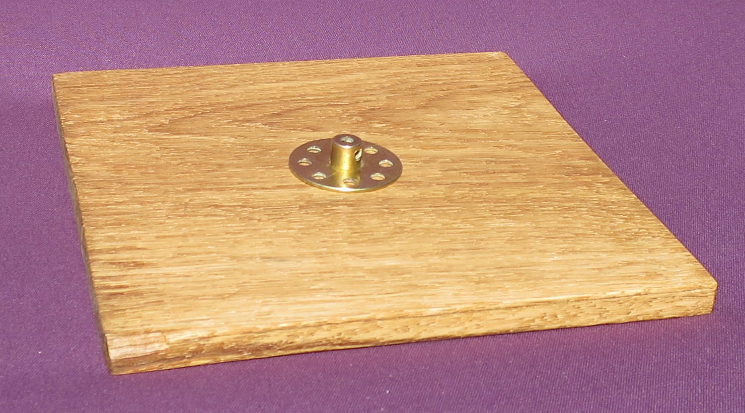
…which is a bit of a mouthful. I think it probably means a table for machines that produce designs, i.e. patterns. And not a table that designs machines. That would require a lot more AI than Meccano could deliver..
This is one of those parts that is pretty much unavailable anywhere, but that doesn’t really matter, as it’s easy enough to make one with basic woodworking skills. And you’ll need one if you want to make one or both of two of the pre-war Super Models: the Meccanograph (no. 13) and the Harmonograph (no.26). Part 107 first appeared in about 1921, was included in the biggest outfits (7 then L) from 1922 until 1936, was not in the 1937 outfit 10, then never reappeared post-war.
To make one you need a piece of hardwood 6 1/2″ by 6 1/2″ by 5/16″. I made mine from an off-cut of an oak floorboard I had lying around in the garage. I had to plane it down a bit to reduce the thickness. It needs a smooth flat finish. Sand it smooth, stain it if you wish, then oil or wax it with a furniture polish. Screw a bush wheel (part 24) to the centre of the underside of the board with 3 or 4 black round-headed screws. 3/8″ no. 6 screws are about right – just make sure they’re not going to stick out of the top of the board. I made my board 3/8″ thick to be on the safe side. Hardwood really needs 1/16″ guide holes drilling before the screws go in – again be careful not to drill all the way through the wood, practising beforehand if you’ve not done this before. I tape up the drill with electrical insulation tape to mark the right depth. You’ll probably notice there are no screws in mine in the photo – I was waiting for Amazon to deliver the screws!