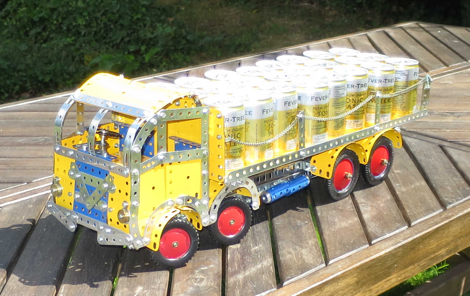
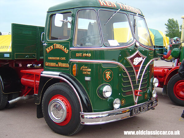
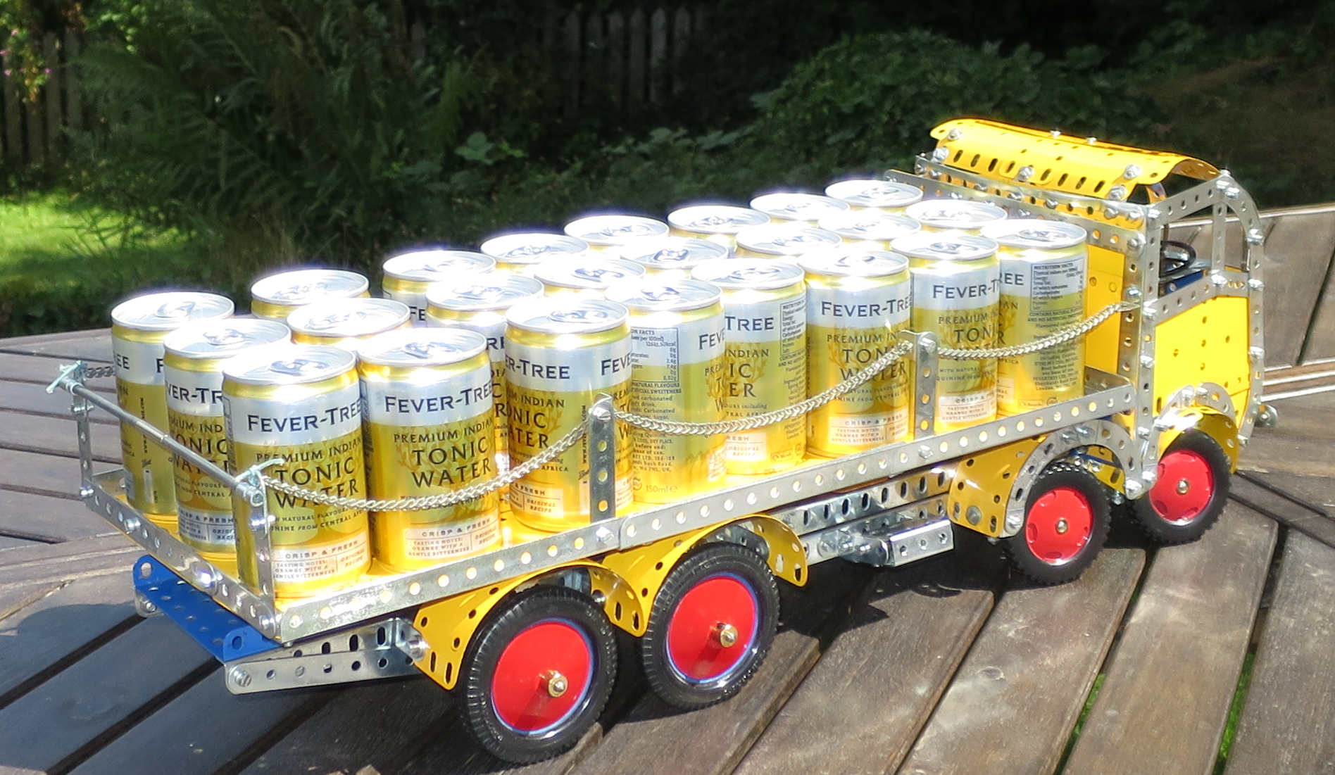
This is a model from the 1955 Meccano Instructions booklet for outfits 7 and 8. It’s numbered 8.19 in the booklet, and is titled ‘Eight-Wheeler Lorry’, but there can be little doubt that the prototype was a 1950s Foden lorry used for delivering barrels to pubs. Here’s a similar Foden cab:
The model is built using my 1970s blue/yellow Meccano, and is pretty much as the instructions given in the booklet. There’s no suspension or cab floor, but that’s fair enough for an outfit 8 model I think. It looks pretty good, particularly once loaded up with tonic water. That won’t go to waste: I’ve got the gin to go with it.
The build was a bit fiddly in places. There are so many nuts inside the cab with no easy access to get your fingers or spanner in, whichever order you put the thing together. And the two front axles are 3 3/4″ apart, and as specified the rear of the two is significantly lower then the other 3 axles. This took a bit of sorting out. The latter issue I resolved by:
(1) I used 1″ by 1/2″ angle brackets to mount the axle rather than the 1″ by 1″ brackets, to take advantage of the long hole in the smaller brackets. I suspect this was the original intention and the text is incorrect, as the smaller brackets are on the parts list anyway.
(2) I also added a couple of washers to each of the double brackets, raising the axle up a bit more.
As for the non-standard distance between the axles, this matters because the steering needs a strip 3 3/4″ long between holes to keep the angles of the two sets of wheels synchronised. The leaflet does this with a 2 1/2″ strip and three fishplates bolted end to end, but this is just asking for trouble. They’ll just keep coming loose. Instead I used a 3 1/2″ strip, a 5-hole 2″ strip and a 2″ perforated slotted strip, which gave me a strip with holes the right distance apart that wouldn’t bend on me.
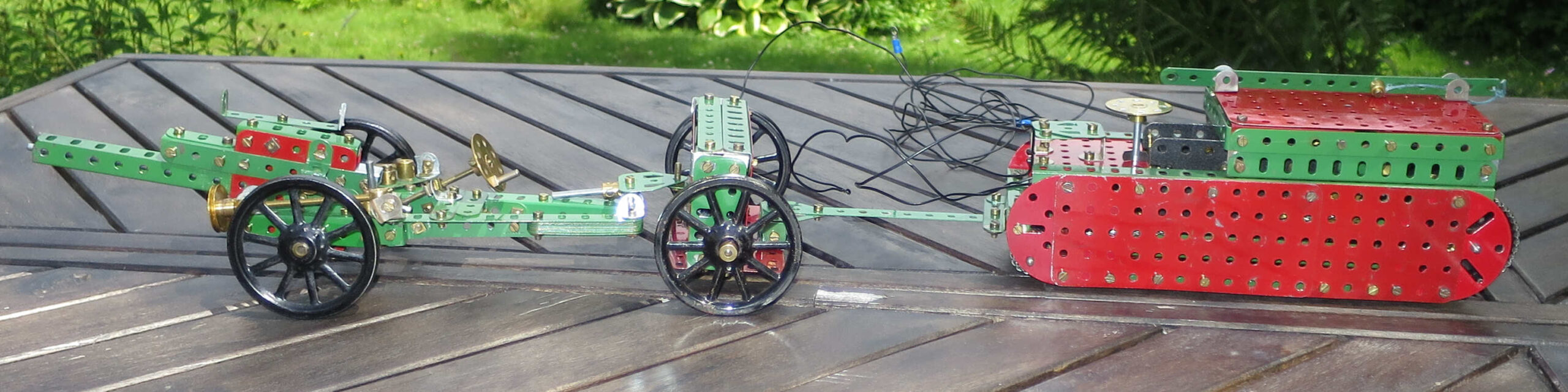
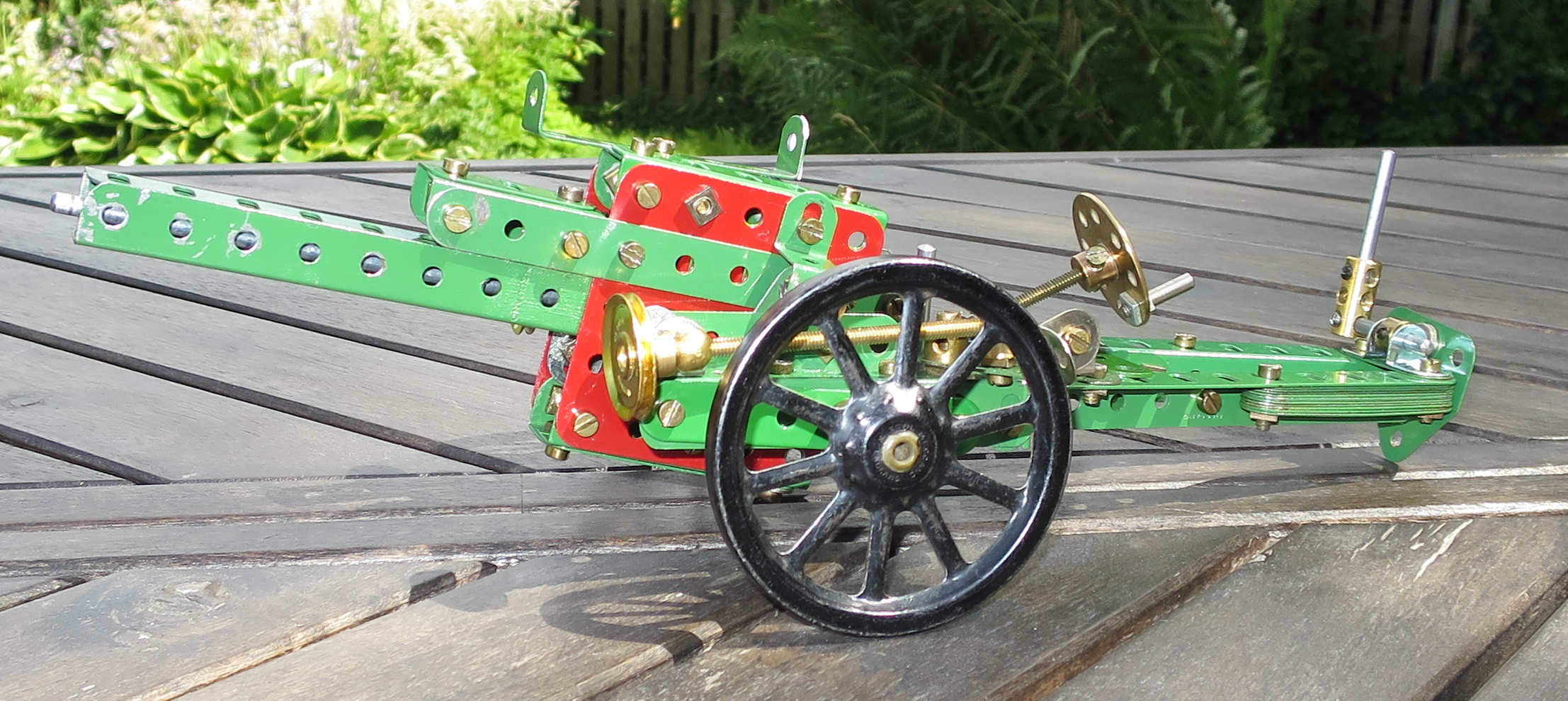
The full title of this one is ‘6-Inch Howitzer Equipped with Limber and Tractor’. Which is a bit of a mouthful. This is the last in the numbered series of Super Models, first appearing in leaflet form in 1930, and it was included with Outfits 6 and 7. It probably had its origins in a similar model published in the 1916 Meccano Instruction Book, but that was a considerably simpler model without armour on the tractor, and without an operational gun.
The Super Model version very much has an operational gun. The leaflet claims it can fire a Meccano washer up to 30 feet, and I can confirm that it does. Care needs to be taken when loading and firing this model: the washers come out with enough force to do serious damage to someone’s eye, and there’s no safety catch. No statistics on how many Meccano boys were injured by these guns are available, although Meccano did publish more dangerous models, which I hope to build later. With care. Not guns though – I’m not really interested in building military models. The Howitzer is one of the Super Models though, so I had to build this one.
Building the model
This next section is mainly documentation to help anyone else who wants to build this model. Jump to the ‘Limber’ and ‘Tractor’ sections when you get bored with it…
The Howitzer
There are a few key parts missing from the Howitzer parts list:
Two compression springs
An additional 2 1/2″ girder (7 not 6)
An additional two reversed angle brackets (4 not 2)
The Howitzer – the gun carriage
This is made up of two main parts: the gun carriage and the barrel/recoil chamber. The carriage was a pretty straightforward build. The instructions and illustrations are clear enough, and the only things I had to change were the lengths of some of the bolts. The brakes are quite neat, although they lack an effective mechanism to move the brake shoes away from the wheels when the brakes are released.
The Howitzer – the barrel, recoil chamber and firing mechanism
This was a different kettle of ballgames altogether. The instructions and illustrations are as clear as mud. So much is not explained or shown clearly, and I had to try things out and learn from my mistakes a lot. The recoil chamber was reasonably easy to work out with a bit of trial and error. The illustrations aren’t bad, but the instructions don’t really explain what everything is for. For instance it took me a long time to work out that the barrel is supposed to slide along inside the recoil chamber. I’d recommend putting a washer between the long hole of angle bracket 24 (Fig. 4) and the flat plate, so the bracket can clear the girder. I’d also recommend adding a second similar angle bracket 1″ further back along the flat plate so the barrel is less free to wiggle up and down. I also mounted the sighting apparatus 2 1/2″ double angle strip 34 (Fig. 2) to the top of the recoil chamber with a 1″ screwed rod rather than a short bolt: it gave better control of the movement of the strip.
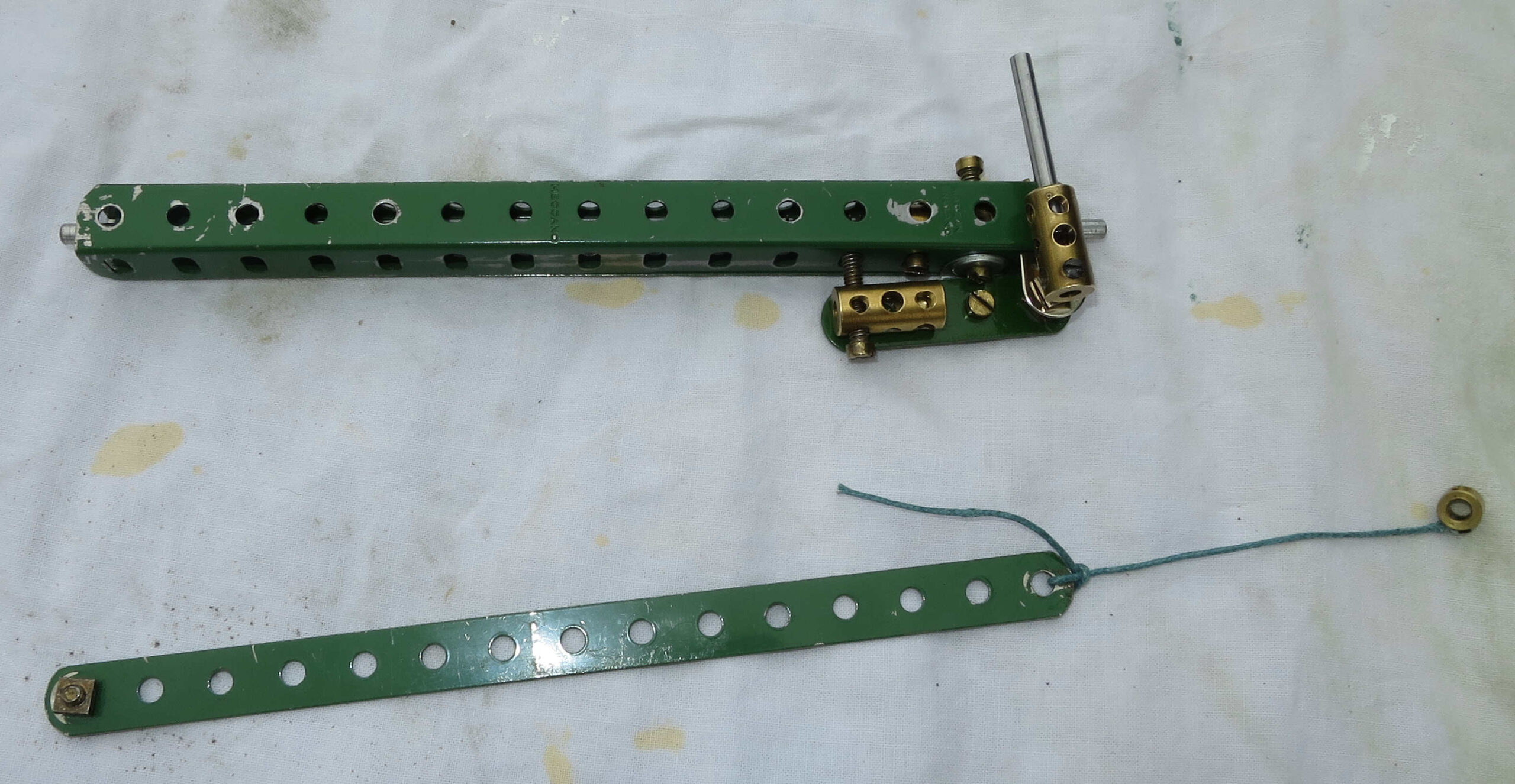
And so to the barrel. The illustrations and instructions are both hopeless. Maybe in the original leaflet the pictures were clearer, but in my Geoff Wright reprint book they are really not enough to work out what’s going on. In the exploded views I couldn’t even tell which way was up. In case anyone else wants to build this model, I’ll try to make things clearer. First a photo of the left-hand side of the barrel and firing mechanism, together with the ramrod:
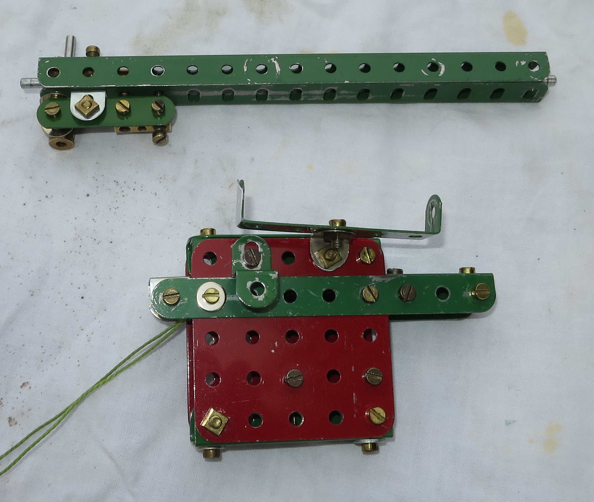
…and the right-hand side of the barrel and recoil chamber. Note the loop of cord on the recoil chamber, used to get the recoil spring in place (covered later on):
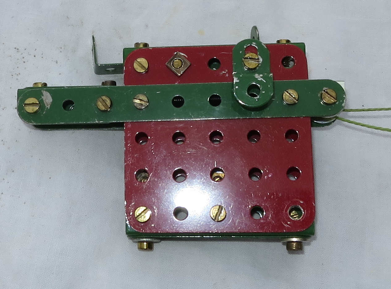
…and for completeness, here’s the left-hand side of the recoil chamber:
Notes:
The elongated holes in the girders 15 and 15a (ref Fig. 4 in the leaflet) are at the top and bottom. Aim to assemble the box section wider rather than taller, i.e. when looking down from above you should be able to see one edge of the underneath girder.
There are no bolts or anything else attached to the sides of the girders. This means it can slide freely inside the recoil chamber.
There are no bolts or anything else attached to the top of the girders, apart from the rear 1″.
There are no bolts or anything else attached to the bottom of the girders, apart from the rear 2″.
Inside the girders, starting from the rear are a coupling 16, a collar 18, and two compression springs (the latter are missing from the leaflet parts list). Through all of these runs an 8″ rod, which needs to be polished shiny if you want to reach 30ft with it. The compression springs need to be overlapped together – 2 or 3 turns is enough. The rear end turn of the rear spring needs to be bent down 90 degrees.
The bolts in the top girder: The end hole holds a set screw with a washer on, which goes through the girder, then another washer, then screws into the rear end of coupling 16. The next hole holds 3/8″ bolt 17 (which will later have a tension spring on it), which then goes through the girder and a washer and also screws into the coupling. The other end of the spring needs to be attached to 3/8″ bolt 29 of the recoil chamber (see Fig. 4), and this needs doing before trying to fix the spring to bolt 17, as you won’t be able to get at bolt 29 once the barrel is in place.
The bolts in the bottom girder: The end hole holds angle bracket 21, part of the firing mechanism. A set screw goes through the round hole of the angle bracket, then the girder, then a washer, then screws into coupling 16. The angle bracket needs to be on the left-hand side of the barrel. The second hole in the girder holds angle bracket 20, also part of the firing mechanism. A set screw goes through a washer, the round hole of the angle bracket, the girder, another washer, then screws into coupling 16. This angle bracket needs to be on the right-hand side of the barrel. The third hole is used to fix collar 18 and the compression springs in place. A set screw goes into the girder then through the bent over end of the rear compression spring and screws into the collar. Note that the collar needs to be spaced a short distance away from coupling 16 to make this work. The fourth hole in the bottom of the girder will hold the end of the bolt acting as the firing catch (3/4″ bolt 22, see Fig. 4 and below).
The various bolts holding the barrel and the 8″ rod will need adjusting to make sure that the rod is mounted centrally all the way along.
The firing mechanism is also difficult to work out from the leaflet. If you’re trying to build this, the photos above should help. Some additional notes:
Fix the firing handle 19 (a 1 1/2″ rod) into the end hole of a coupling.
Fix a 3/4″ bolt to the end hole of a 2″ strip, and tighten the nut well. This is the rear end of the 2″ strip, which will end up being mounted about 1/2″ below the rear end of the barrel, with this bolt head on the right-hand side.
Fix a coupling to the other end of the 2″ strip so it lies alongside the end two holes of the strip. Both bolts should be fed in from the same side of the strip as the 3/4″ bolt was. Use a set screw for the end bolt – the shortest one you’ve got. This set screw holds in place 3/4″ bolt 22, which you feed through the coupling from below (i.e. if you’re looking at the strip from the bolt-head side, with this bolt on the right, feed the 3/4″ bolt up from below and tighten the set screw on it). You can use a normal bolt for the second hole in the strip, which fixes the strip securely to the coupling.
You are now ready to fix the 2″ strip to the barrel. This is a fiddly job as:
You need to make sure the front two bolts and the coupling don’t stick out widthways beyond the profile of the barrel. If they do, they won’t go through the recoil chamber.
The 3/4″ bolt 22 needs to move slightly in and out of the fourth hole in the barrel when you move the firing handle. It doesn’t need to come out completely though.
Put a bolt through the remaining hole in the 2″ strip, from the opposite side from the other bolts, and lock-nut it to angle bracket 20, the one on the second hole of the barrel. Lock-nut with a nut each side of the bracket, locking the bolt to the bracket, at the bottom end of the bracket’s long hole, i.e. away from the barrel. The strip needs to be on the left-hand side of the bracket, and at the same time you will be feeding the 3/4″ bolt in the adjacent hole of the strip through angle bracket 21, and the other 3/4″ bolt 22 should feed into the fourth hole of the barrel.
Now fix the bottom end of the firing handle coupling to the rear 3/4″ bolt so they are at right angles to each other and the firing handle points upwards (see Fig. 2). I did this by putting a nut on the bolt, screwing the coupling on to the threaded hole of the coupling, then lock-nutting the nut to the coupling. This seems to stay tightened better than the alternative of using the unthreaded hole of the coupling and securing it with bolts or grub screws.
Loading and firing
Firstly I need to reiterate that this gun is potentially dangerous, particularly to the eyes. From the moment I compressed the spring to the moment it fired I was careful never to point the barrel at anyone, including myself. It could go off at any time without warning. Looking up the barrel to find out what’s gone wrong is not a good plan.
According to the leaflet, you can just push a washer down the barrel with a 7 1/2″ strip, but this doesn’t really work. Pushing a washer with a strip just jams the washer sideways. What does work, after a fashion, is putting a collar on the rod after the washer, and pushing them both with the strip. You can then, with luck, get the 3/4″ bolt to catch the edge of the washer and hold it there. The trouble is, you’ve now no way of getting the collar out again other than firing it along with the washer (and it will go nearly as far, by the way). In any event, catching the edge of the washer with the bolt was pretty tricky, and the gun was liable to fire on its own. After trying out a few possible improvements I ended up using an aero collar rather than a normal collar. An aero collar (part P52) is slightly smaller in diameter than a normal collar, and this gave more of a lip to catch with the bolt, improving the reliability of the catch mechanism. I also fixed a short length of cord to the collar by trapping it in with a short grub screw (part 69c), and tied the other end of the cord to the 7 1/2″ strip, so I could retrieve the collar with the strip. Even with this approach, getting the bolt to catch on the edge of the washer was not at all easy. And it was even harder when the barrel was fitted to the rest of the howitzer, as I couldn’t see what I was doing.
Fitting the recoil spring
Once the gun appeared to fire reasonably well, the barrel needed to be fixed into the recoil chamber with the recoil spring. You can’t access the front end of the spring with the barrel in place, so I needed to fix the spring to the front 3/8″ bolt 29 (Fig. 4) first. I first fixed this bolt in place with a nut. Then I tied a loop of cord to each end of my tension spring and fed one loop through the recoil chamber and hooked the spring over bolt 29. My reed hook came in handy here. I lock-nutted two nuts over the bolt, securing the front end of the spring. Then I inserted the barrel, carefully removed the 3/8″ bolt 17 from the barrel, pulled the other cord loop to stretch the spring, and replaced bolt 17 securing the back end of the spring. This was fiddly. Then I removed both cord loops.
Fitting the gun to the gun carriage
I hoped this was going to be straightforward, but it wasn’t. First I had to adjust the recoil chamber a bit so I could feed the 2 1/2″ rod through it. That would have been easy if it wasn’t for the fact that the recoil spring was in the way. The spring needs to run over the top of the rod, and in order to push the rod through you need to hook the spring up out of the way temporarily. OK, so I did this using my trusty reed hook again, and got the rod through. It doesn’t need to run freely, as it will journal in the two triangular plates 30 (Figs. 2 and 3) on the carriage.
But you can’t just fit the gun onto the carriage with the rod in place. You have to feed the rod through one triangular plate, through the recoil chamber, then through the other triangular plate, adding collars along the way, and all the time keeping the recoil spring out of the way. It needed about five hands. By the time I’d done all that I’d had enough for the day. And the barrel was no longer running freely in the recoil chamber, so I had to fix that too.
The elevating apparatus was easy enough to sort out. It needs a 4 1/2″ screwed road as per the parts list, not the 3 1/2″ rod the text specifies. I used two pairs of nuts, each pair lock-nutted together, rather than two collars to hold the rod in place – it works better. I bent the angle bracket out to about 110 degrees.
The Limber
This was easy to build. You need plenty of washers if you want to load it full of ammo. Which is what the limber is for.
The Tractor
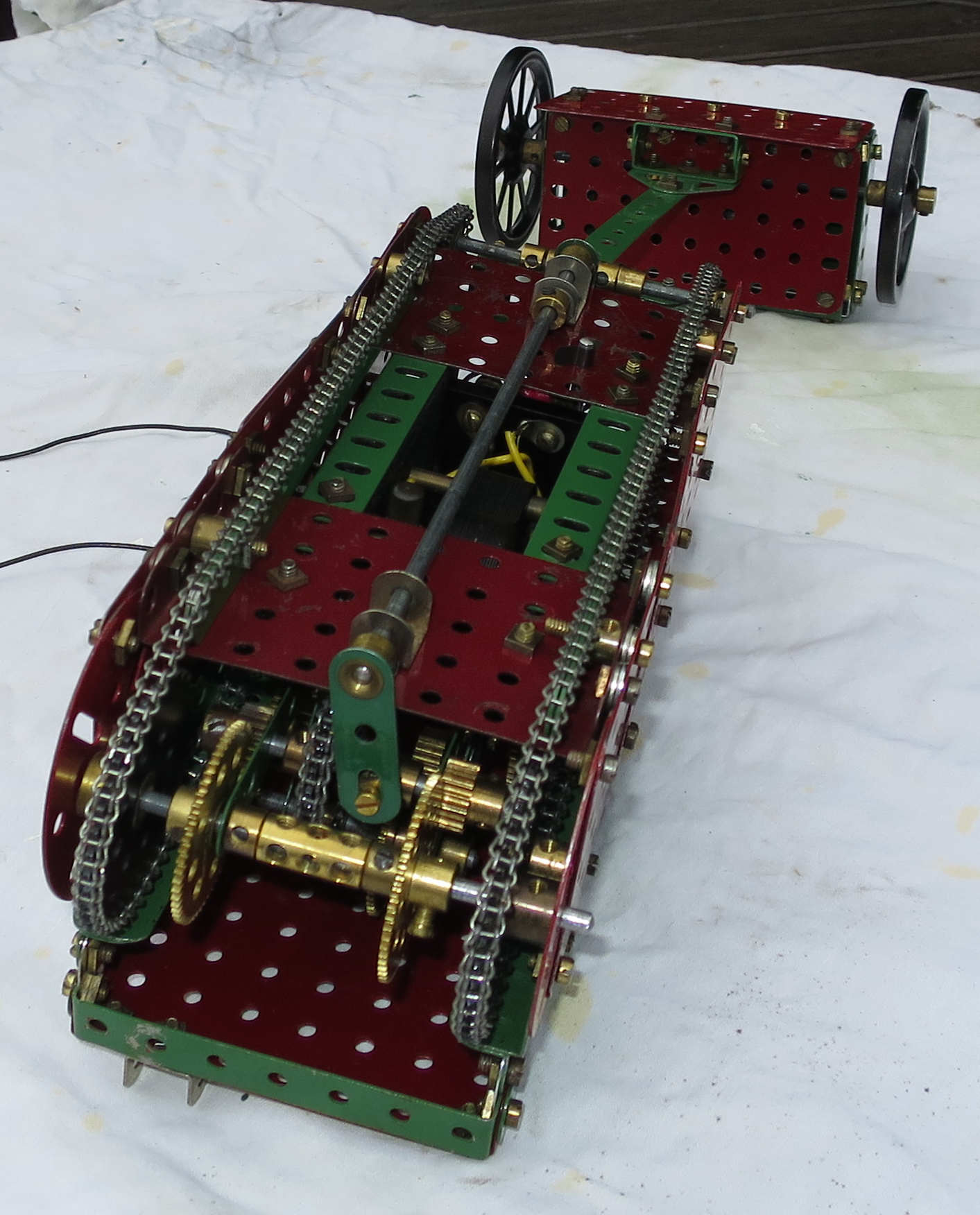
The beetle on its back:
This was interesting, and a bit tricky in places. It’s got caterpillar tracks made from sprocket chain, and they don’t really work very well. It’s an impressive design attempt though. I’d have liked to try slowing the sprocket chains down a bit, but there was so little space to do it. Visually, the tractor looks like a metal brick, but I suppose that’s fair enough, considering what it’s representing. Working on the tractor was fiddly, as there’s a lot crammed into a small box.
I had to extend my 1950s motor by 1″ at the top front using 1″ corner brackets, and you need three 1/2″ pinions for the gear train, not the two quoted in the parts list.
There are a couple of significant mistakes in the text of the ‘Building the Tractor’ section of the leaflet. These took me a while to sort out. The first is in sentence 2 where it refers to ‘Four 3 1/2″ x 2 1/2″ Flanged Plates’. You only need three of them. The front top can’t have one, as it would foul the gears. You have to be careful locating the bottom flanged plates: I ended up with the front of the front one directly above the end of girder 39 (Fig. 5), and the back of the back one 1/2″ further forward than the top flanged plate. The second error in the text is in the description of the gear train, where a bit has been missed out. Para 2 sentence 3 should read: ‘This pinion meshes with a 50-teeth Gear on the Rod 40, which also carries a 3/4″ Pinion. This engages with a 50-teeth Gear on the Rod 41, and this Rod carries also a 3/4″ Sprocket Wheel that is connected by Sprocket Chain to a 1″ Sprocket Wheel 42 on a slidable lay-shaft.’
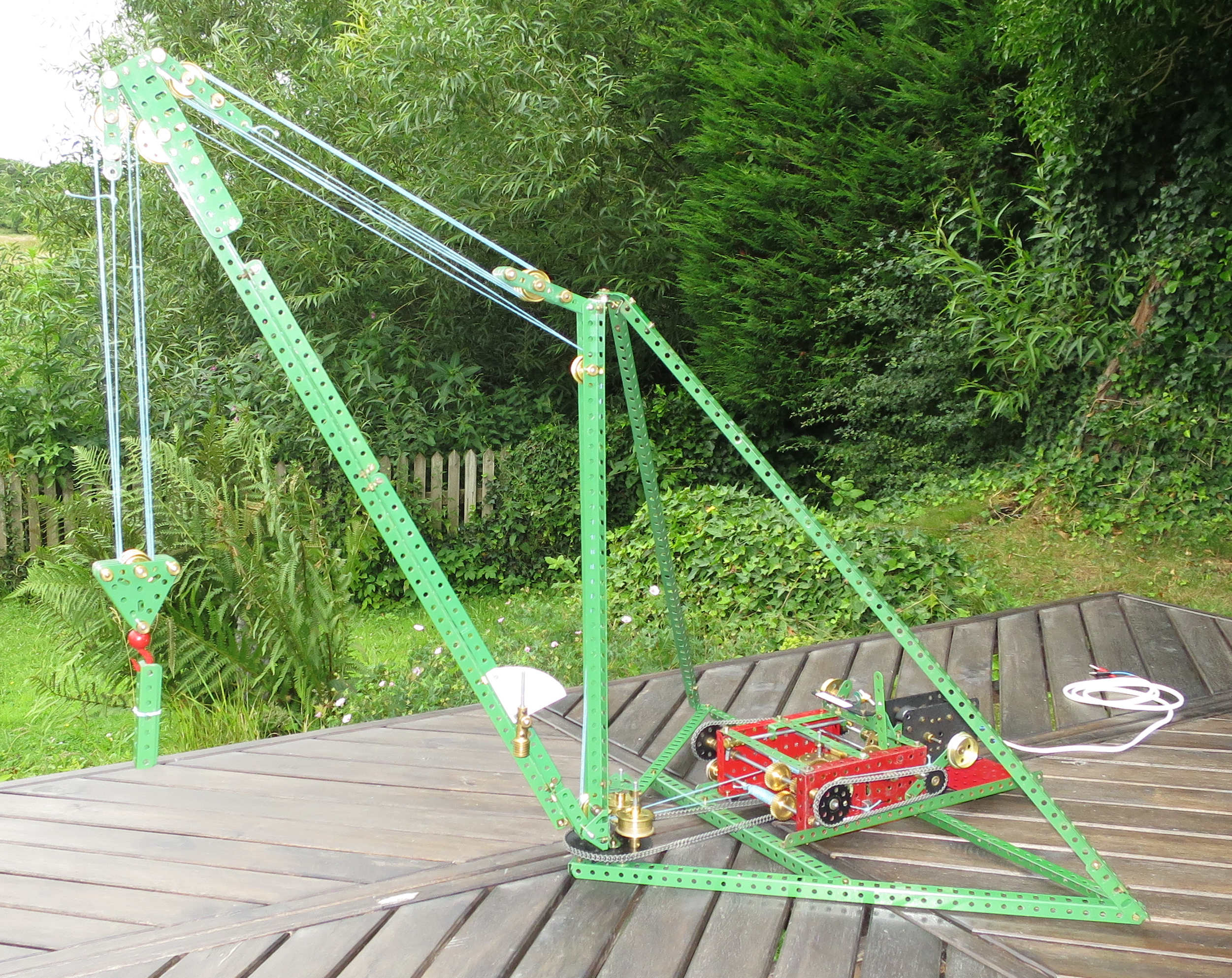
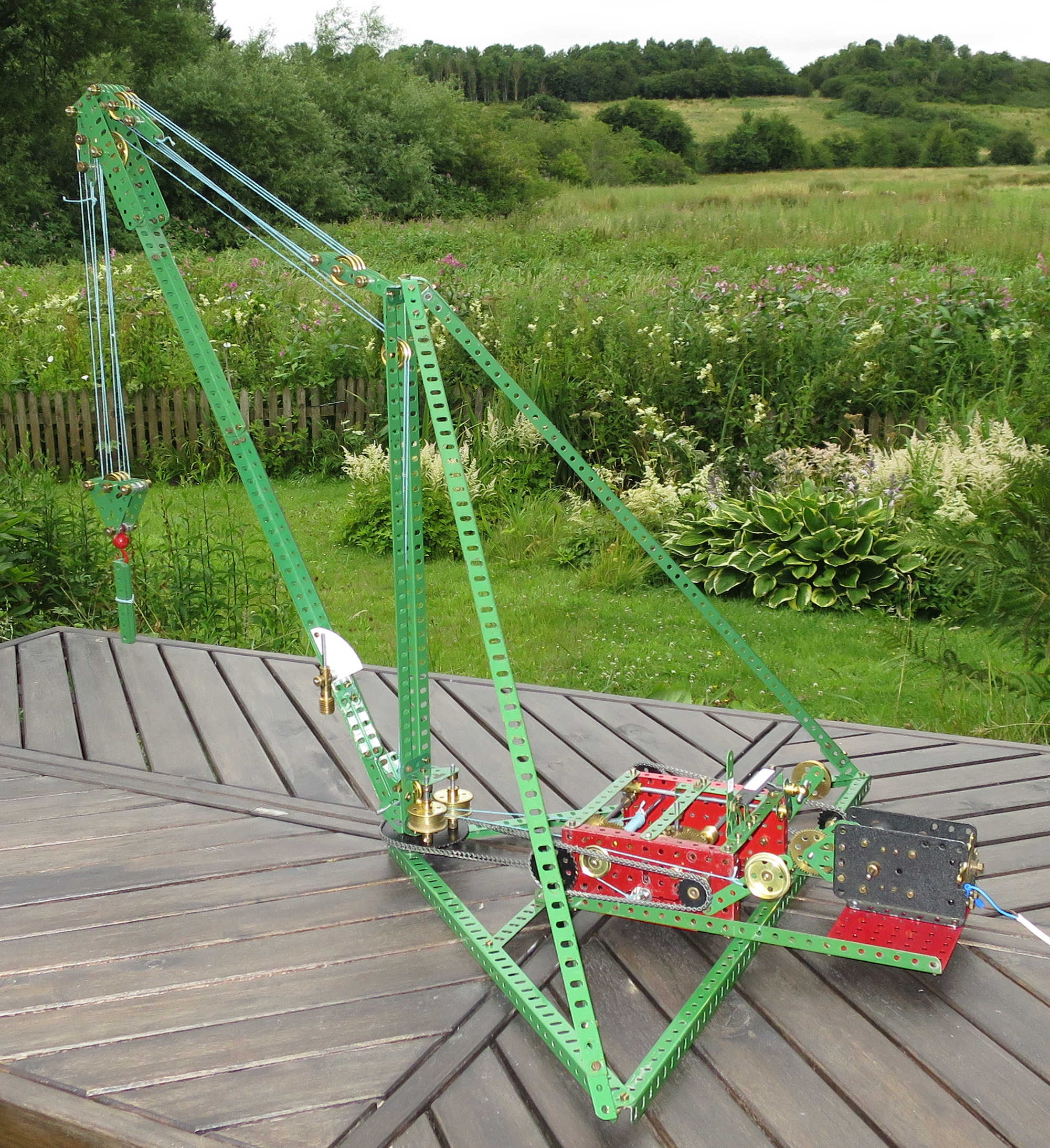
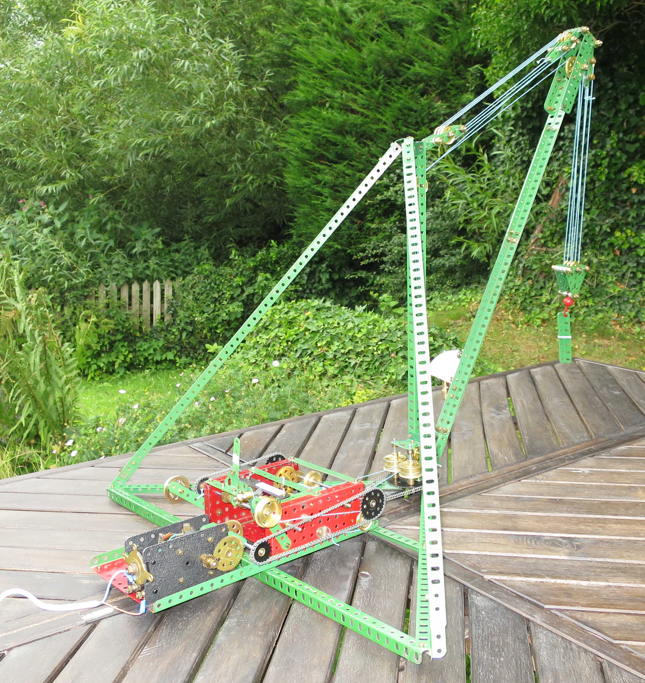
This is Super Model no. 6, and is one of many Meccano cranes. I have to confess I wasn’t really looking forward to building it: in the leaflet it looks very simple and not very impressive. Once built, however, it’s quite an elegant and impressive thing. It’s big, for one thing. What’s more, it works properly – I take my hat off to whoever designed this one.
A smaller version of this model was in the 1916 Meccano Instruction Book 1, and the Super Model version first appeared in 1925. The build instructions were issued in leaflet form from 1928.
The Build
This was reasonably straightforward for a change, and I enjoyed putting it together. Perhaps because it’s a skeletal model, the leaflet pictures show most of the detail you need and there’s relatively little guesswork needed.
As usual the leaflet parts list is incomplete and inaccurate: you need more cogs and sprockets, you need an extra 5 1/2″ strip and four 2 1/2″ angle girders. And the parts for the radius indicator aren’t included in the parts list. On the other hand you don’t need any 3 1/2″ angle girders – the six I had ready I used as a load for the crane instead.
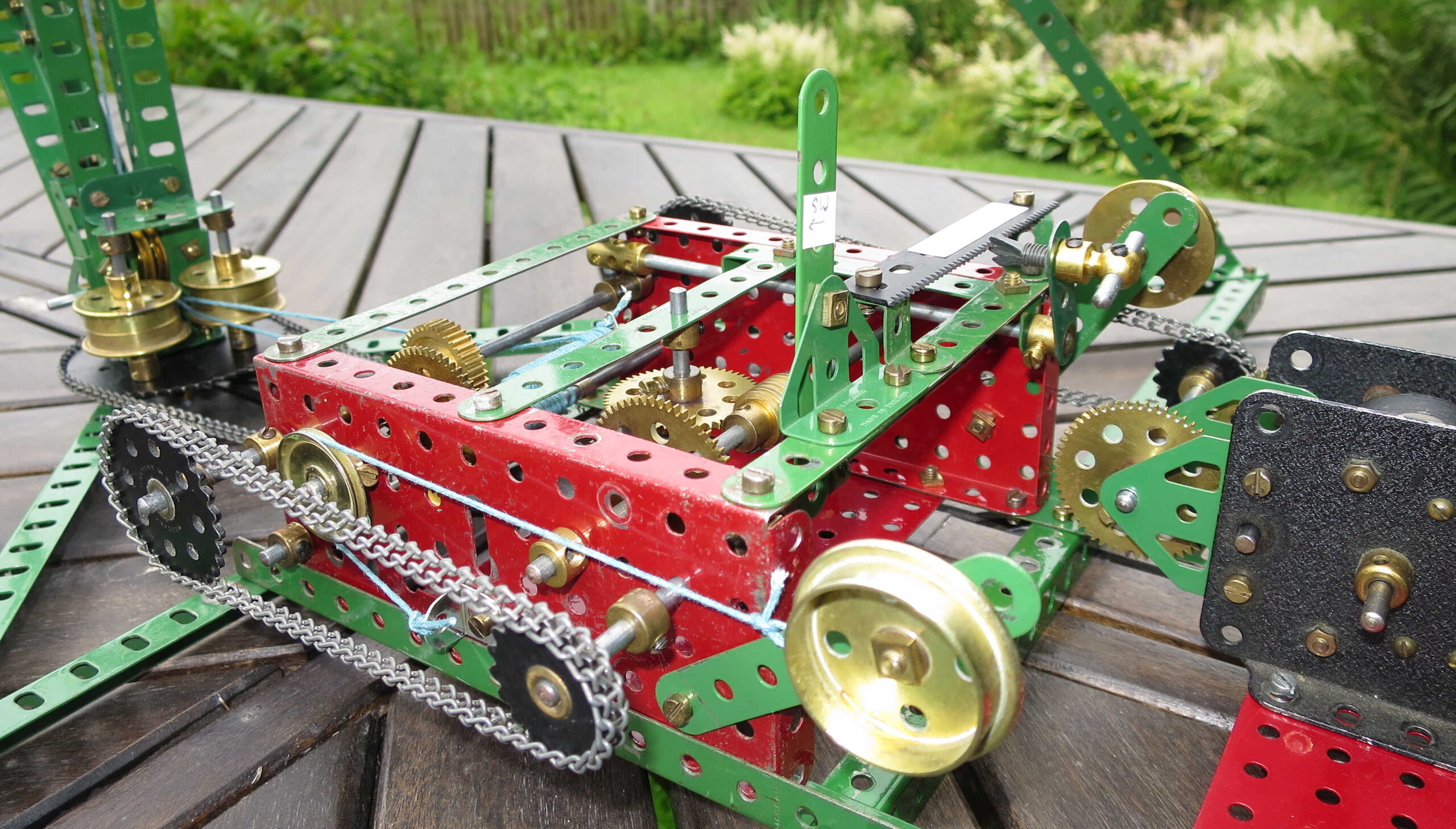
I made one improvement to the gearbox. There are two levers (24 and 26 in Fig. 5) that move rods to change which crane function to engage (rods 16 and 25 in Fig. 5). There’s nothing to stop the levers moving with the vibrations of the motor, and engaging or disengaging cogs when you don’t want that to happen. This is a common problem with Meccano gearboxes, and I’ve fixed it in different ways. This time, it was easy to fix lever 26 by tightening up the bolt fastening it to the trunnion, giving it some friction. Lever 24 needed a bit more thinking about. What I ended up doing was moving lever 26 and the trunnion over by 1″, which made room to mount a short rack strip 1/2″ above and in front of the 5 1/2″ strip (parallel to it), using a couple of reversed angle brackets. The rack strip is there to stop the lever 24 from moving on its own, so I needed the lever to engage intermittently with the rack strip. I put a compression spring onto a centre fork, pushed it through the top hole of lever 24, and fixed a handrail coupling to the fork. This meant I could move the lever by pulling the handrail coupling and centre fork back against the spring, moving the lever sideways, then letting the spring push the centre fork back into a new position on the rack, holding the rod in its new position. A 1″ rod through the handrail coupling made it easier to hold. And I labelled up the three positions on the rack so I’d remember what was what.
Oh, and I used anchoring springs rather than spring clips to anchor the two cords in the gearbox.