Meccano Articulated Tanker

May 2026

Introduction

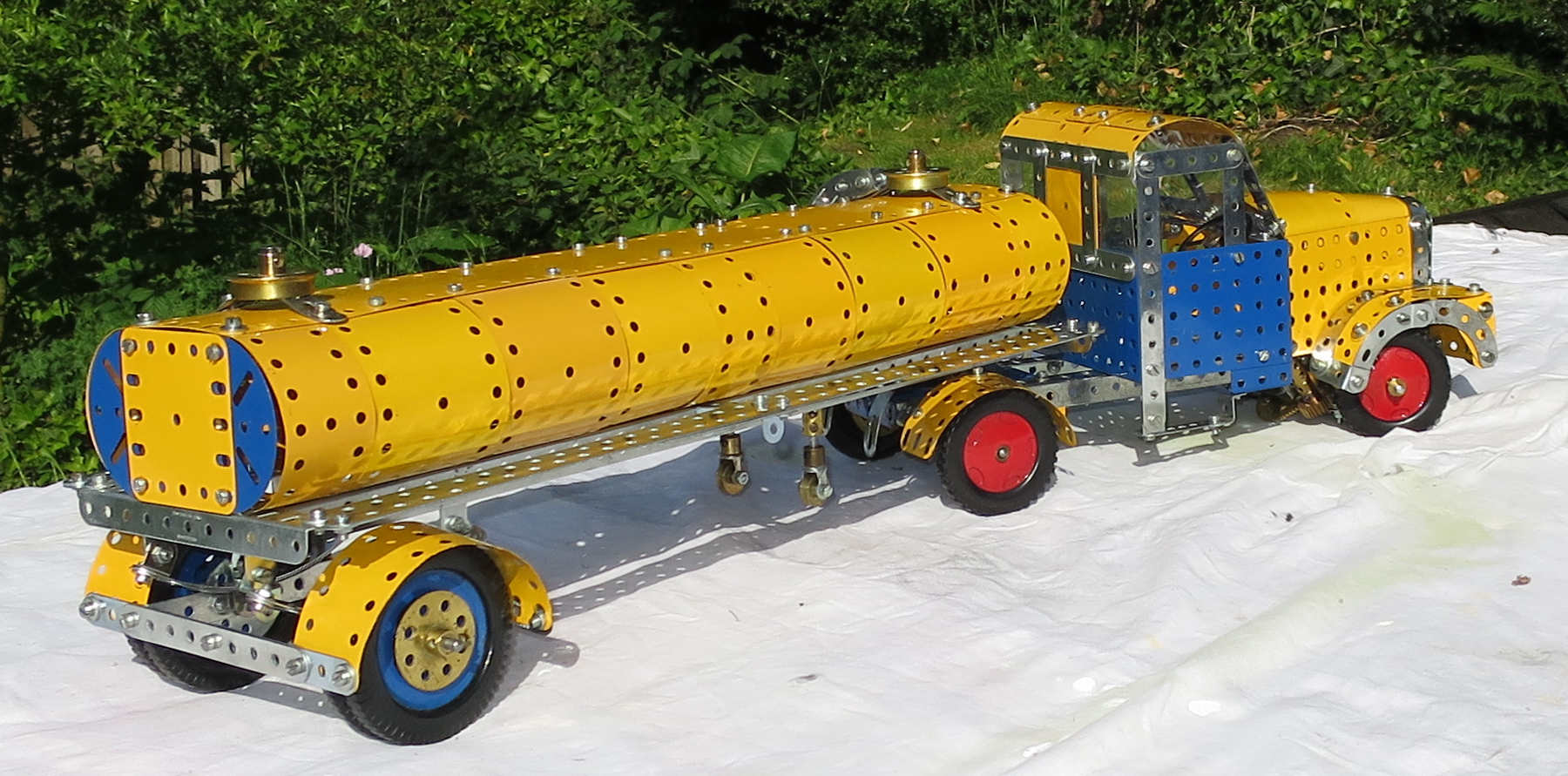
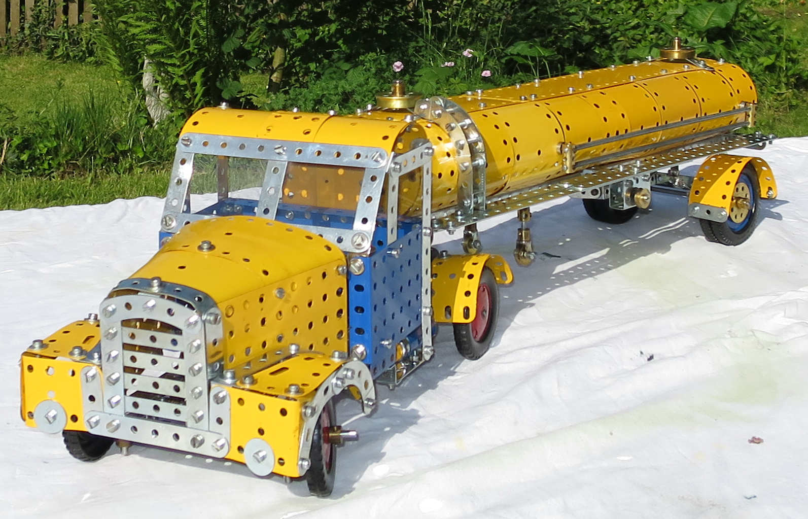
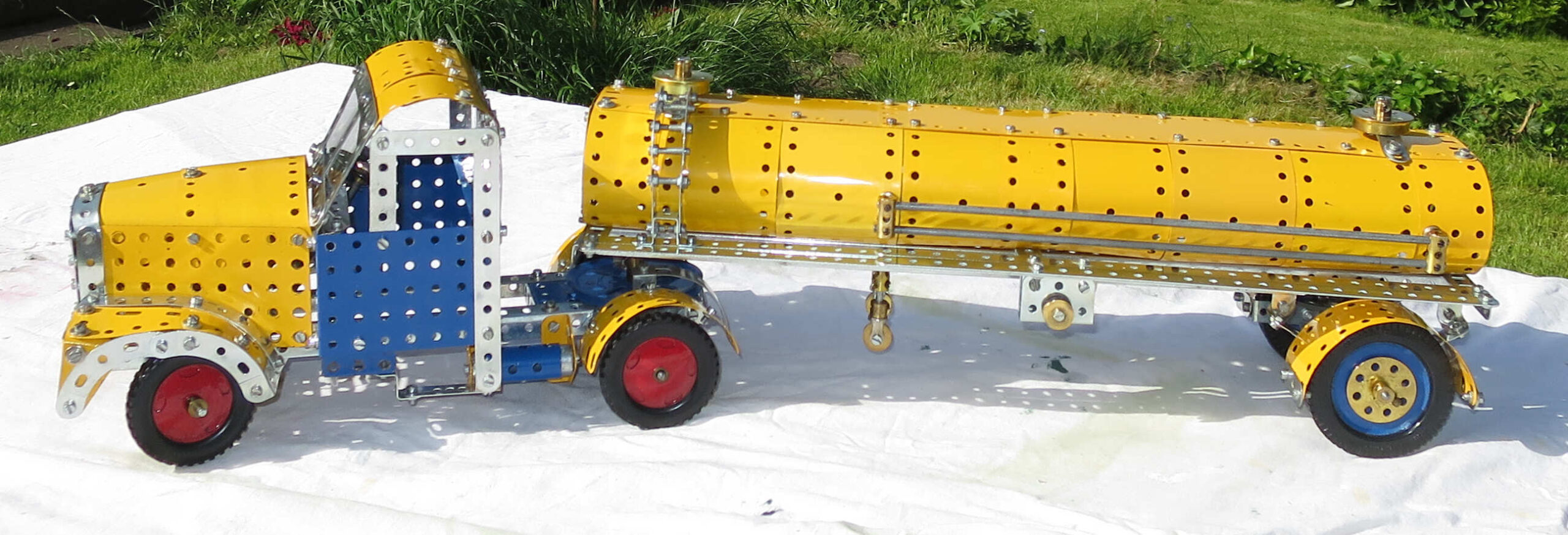
For a break from building the Super Models I thought I’d build something with my 1970s Outfit 9. Although I’ve had this outfit since the 1970s, I’ve never built this particular model – number 9.9 in the 1973 Outfit 9 Book of Models. I think I’d been put off by the amount of strip and plate bending required. Having built a few Super Models, I’m now used to bending my Meccano, so this one no longer held any fears for me. I’ve got a strip roller and I’m going to use it.

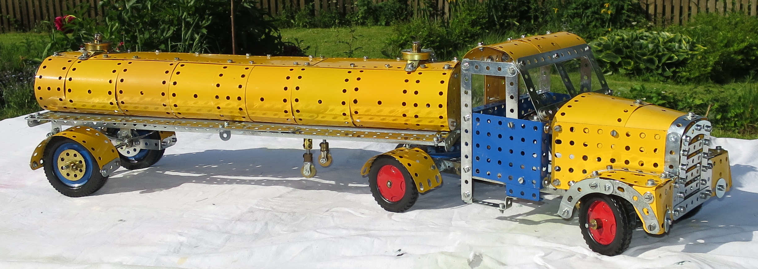
For a 1970s Outfit 9 model, I think it looks pretty good. It’s not motorised, but since there’s no floor to the cab the driver can run along the ground Fred Flintstone-style. It’s got steering (but see below), and the trailer’s even got leaf springs, although they don’t actually spring the trailer – they’re just for show.
Build issues

Firstly, the parts list is seriously incomplete. As long as you’ve got a 1970s Outfit 9 you’ll be OK, but don’t rely on the parts list for this model. I won’t try to list the omissions – there are too many.

Secondly, the steering linkage is really pretty poor. I built it as per the Book of Models, then had to give it some serious improvement to get it to work properly. I replaced the bent 3″ strip (part 4 on diagram) with a 2″ rod and two extra rod and strip connectors (part 212). I ditched the screwed rod, and mounted the gear wheel 27a on a short rod journalled in a 2 1/2″ double angle strip and a double bracket. The double angle strip I bolted to two 1″ triangular plates (part 77), which I bolted to the main girders. This left the gear wheel approximately in the same place as it had been, and far more stable. It didn’t quite mesh with the smaller gear wheel now, but I replaced the 1/2″ gear with a 3/4″ gear, spaced it out from the girder with a couple of washers, and the fit was good. Now the steering was solid enough, apart from the steering column not being journalled in anything at the top. A long bolt through the dashboard and a collar onto an obtuse angle bracket fixed this. Incidentally the steering column is missing from the parts list, requires a 4″ rod according the diagram, and now needed a 4 1/2″ rod after my redesign. (What the anchoring spring and wheel disc were doing in the original design is anyone’s guess. And they weren’t in the parts list either.)

Thirdly, don’t use four obtuse angle brackets to attach the bonnet to the cab, as shown in the diagram. The angle’s completely wrong. You just need to open up four ordinary angle brackets very slightly. This was not fun to go back and fix.

Fourthly, the trailer mudguard assembly wouldn’t fit over the 2 1/2″ by 1″ double angle strips – the mudguards were forced to splay apart. I tried getting the mudguards further apart but there’s little give there. What did work was remounting the angle brackets fixing the springs to the double angle strips so they were inside the strips. It gained about 1/10″ but that’s all it needed.

Fifthly, and finally, getting the trailer’s axle to run freely took quite a bit of work. There is a design problem here. A wheel disc is used to journal the axle, and also to secure the mudguard/axle assembly in place. These two fixings are 1/2″ apart on the wheel disc. The corresponding fixing points on the spring assembly are more than 1/2″ apart – a double bracket, three thicknesses of strip in the spring, and an angle bracket. Even with the long hole on the angle bracket. So the axle won’t run freely. I tried a few possible fixes, and ended up replacing the two double brackets with pairs of angle brackets, journalling the axle in the long holes of the angle brackets. This worked, as long as I didn’t overtighten up the bolts fixing the wheel disc to the angle brackets above the springs. Tightening these bolts twisted something, locking the axle up again. In the end I fixed this by adding washer shims between the wheel discs and the angle brackets.

Two more photos:
Meccano Hydraulic Crane

May 2026

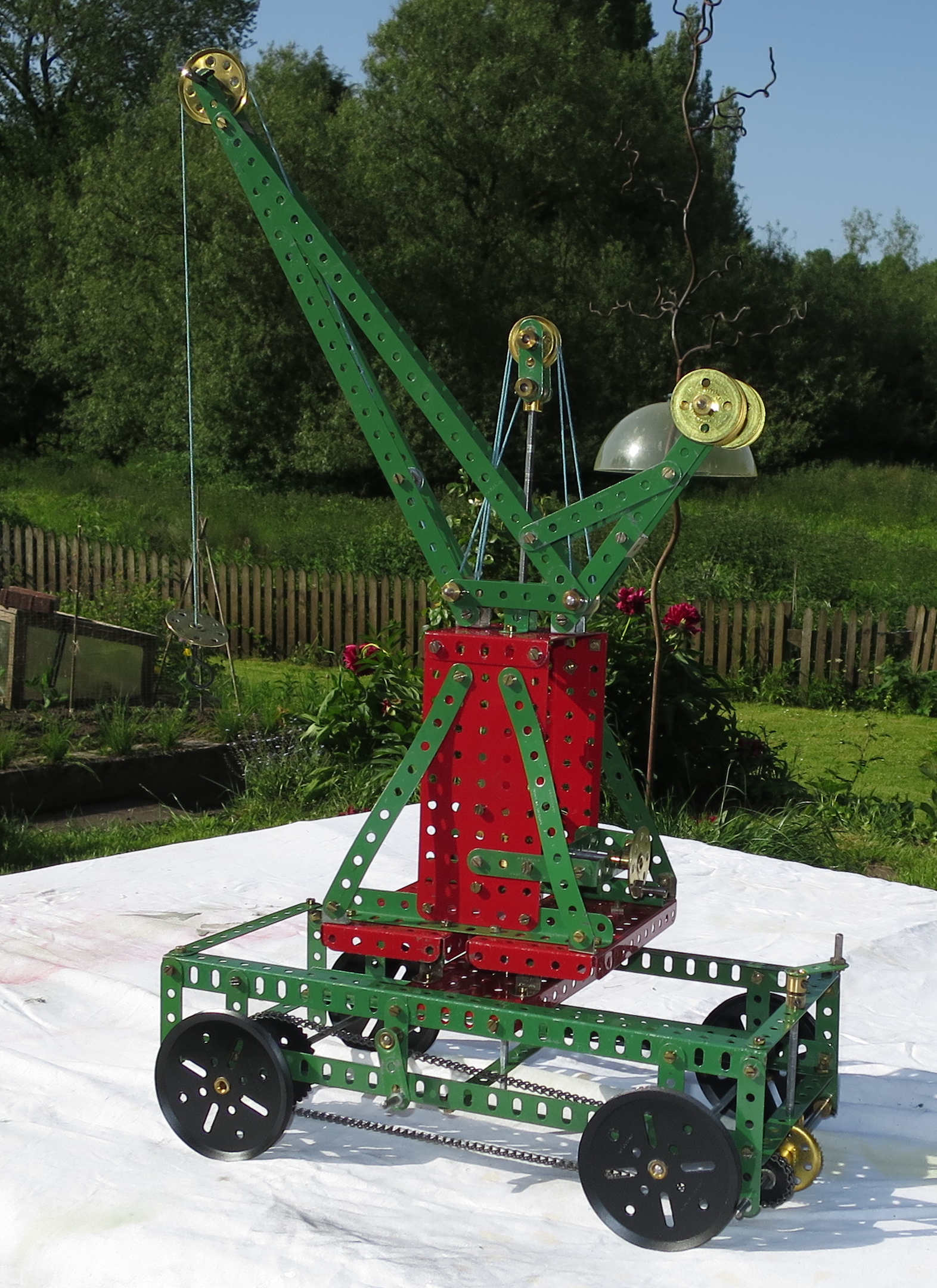
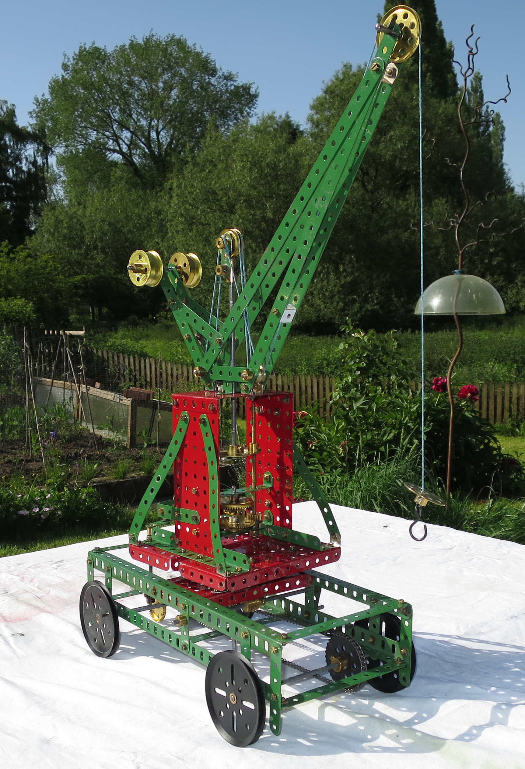
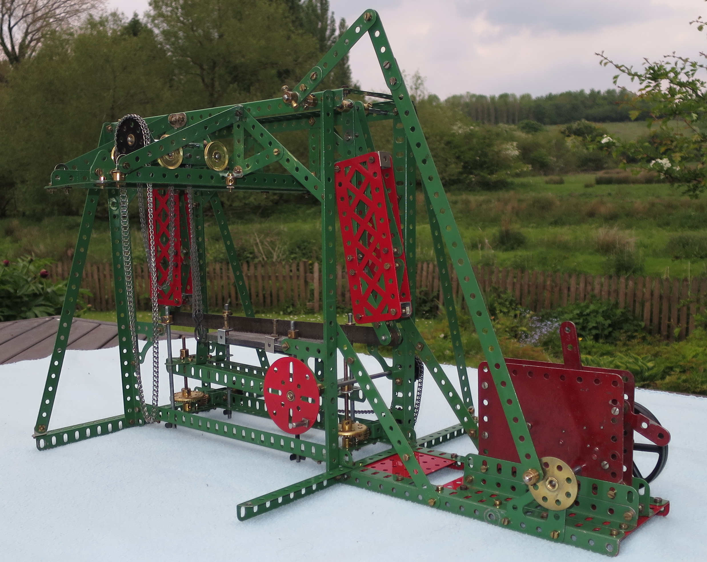
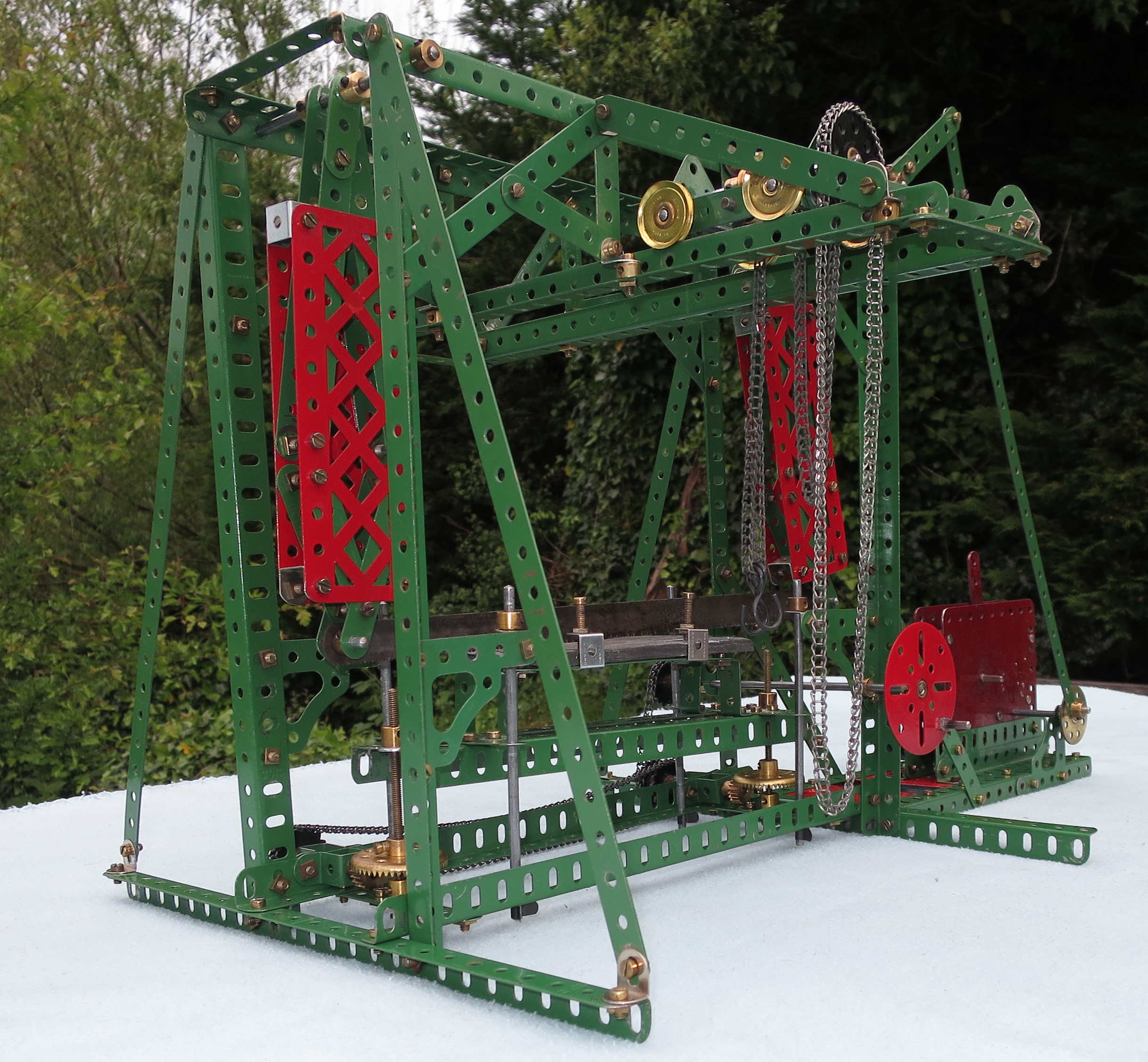
To be honest I just built this one to get it ticked off. I’m trying to build all the 1920s/30s Super Models, and this is one of them – number 25. It’s just not that super. It’s based on a hydraulic-powered crane, but doesn’t really convince as that, since there’s little sign of hydraulics, or anything looking like them. The prototype runs on rails, but the model won’t, as there’s no flanges to the wheels. And it’s not very big and not very complicated. It did, however, win a prize in a Meccano competition, and appeared on the front of Meccano Magazine in the January/February 1921 issue.

I didn’t have any problems with the build really. There are a few things missing from the parts list, as usual, of course. You need a couple of 3/8″ bolts to attach bush wheel 8 (fig. 3) to the cranks 7, and careful adjustment is needed to get the friction on the screwed rods down to a reasonable level. You need a 1″ sprocket, and two 1″ rods. And Fig. 2 shows a 3″ strip vertically at each corner, whereas the parts list seems to assume that two of them are 2 1/2″ strips. Either works though. I also used 6 1/2″ rods for the axles instead of 8″ rods – it looks better that way.

This simple model was included with the old Outfit 7, but wasn’t in Outfit 6. I can’t see why not – the only extra parts needed were two 5″ screwed rods and a third threaded pin. 4 1/2″ screwed rods would work just as well, and they were in Outfit 6. And a long bolt would have substituted for one of the threaded pins. I guess we’ll never know…

Meccano Stone-Sawing Machine

May 2026

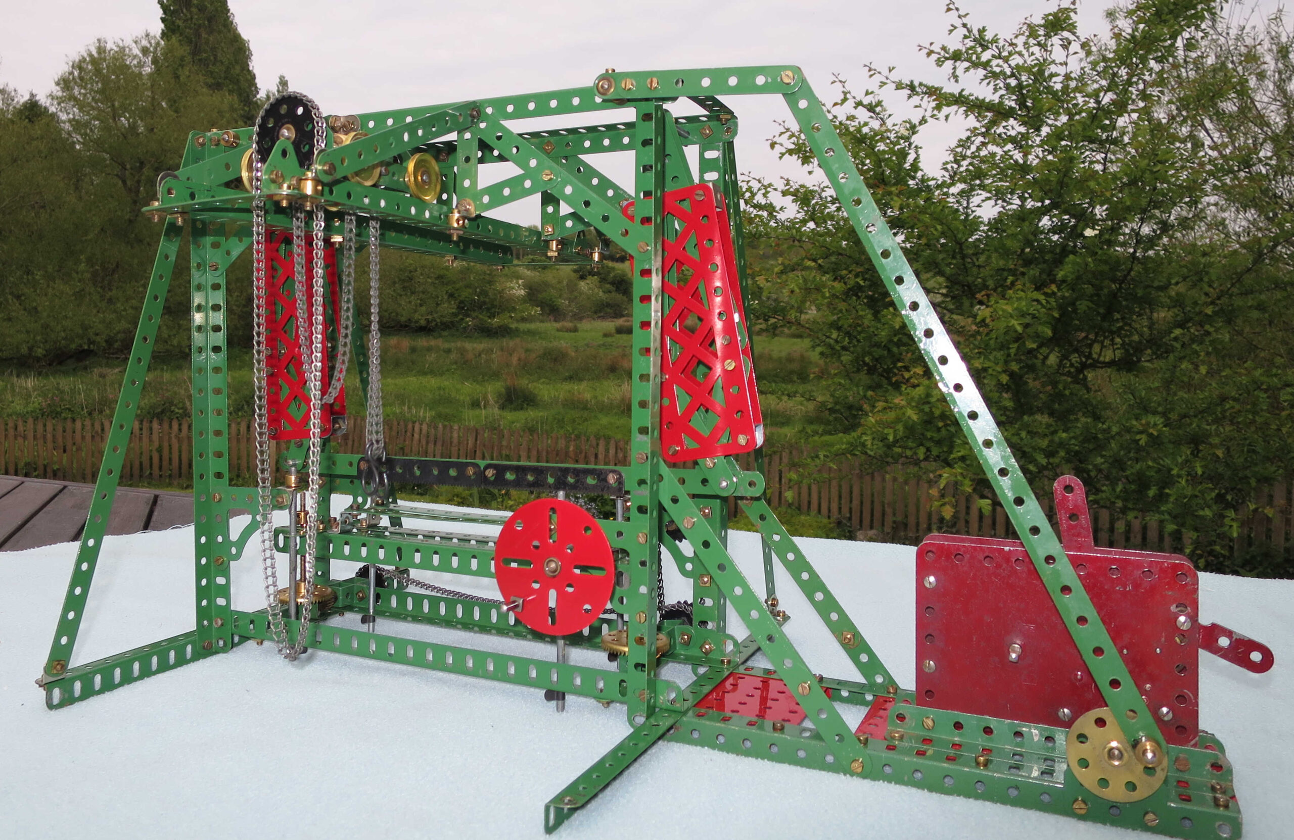
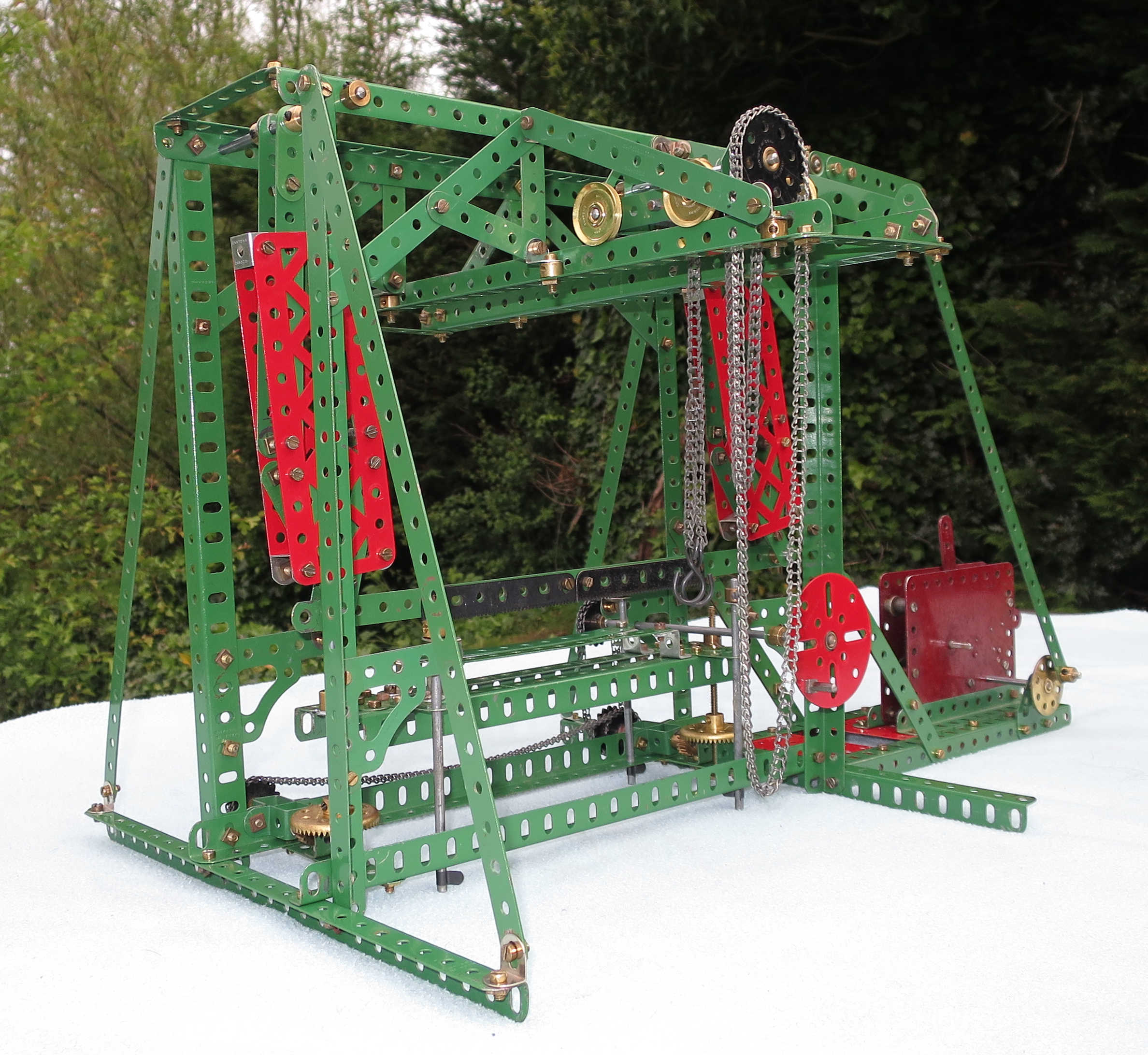
This is Super Model number 12, which I completed in early May 2026 after dismantling the Baltic Tank Loco. I couldn’t really build anything until I’d taken the loco to bits as it used so many of my parts, including all my nuts and bolts. My trusty parts spreadsheet told me I had enough parts to be able to build four of the smaller Super Models, so my plan is to build all four over the summer and take them to meets in the autumn. The stone saw is the first of these, and probably the most interesting – to me anyway. As far as I know, it made its first appearance in the 1916 Meccano Instruction Book 1.

First impressions

This is the first model I’ve built using a 1930s clockwork motor, and I was sceptical as to whether it would actually be able to saw through stone. Nevertheless I was going to try. But first I wanted to build the model as illustrated in the leaflet (see photo above). This uses rack strips to represent the saw blade, so clearly can’t actually saw anything.

So I gathered the parts together on a tray, as I generally do. As usual the parts list in the leaflet left something to be desired. It called for 12 of part number 7, which are of course 24.5″ angle girders. It doesn’t need any 24.5″ angle girders, and that should read 12 of part number 8, i.e. 12.5″ angle girders. Not a good start. It turned out that there are also a few things missing altogether from the parts list:

  1. 4 more 2.5″ strips (part 5)
  2. 4 more angle brackets (part 12)
  3. 8 x 0.5″ bolts (part 111a, to mount collars)
  4. 4 x 1″ sprockets (part 96)

Additionally, the list of rods given aren’t the best lengths for the job, and I’d guess they were constrained by the statement on the front of the leaflet: “a No. 6 Outfit Model”. Oh, and it turns out the model doesn’t really use a 2.5″ x 1.5″ double angle strip (part 47) or 3 of the 5 2.5″ x 1.5″ double angle strips (part 48a).

The initial build

The build was mostly straightforward, as it’s not a very complex model. The main problem I hit was in building the gantry rails – the track for the overhead trolley to run on. What’s not made clear in the text or the photos is that the gantry rails are not central in the model. They are halfway between the two ends of the saw, but the middle point of the rails is not over the saw. The 5.5″ strips (77 in fig. 2) are only at the front of the model, i.e. above the work table wheel. They bolt to the penultimate holes of the gantry rail 12.5″ girders (24 in figs. 1 and 2), not the third holes from the end, despite what figs. 1 and 2 seem to show. And the equivalent strips to 77 at the back are 3.5″ strips, bolted to the end holes of the girders. All that took a fair bit of working out.

The motor moved the saw, and I was reasonably happy with the model, but it was clearly going to need more than just the addition of a hacksaw blade to get it sawing stone. And the eagle-eyed may notice that I’d mounted the table adjustment wheel in the wrong place.

The working version

To quote from the Super Model leaflet: ‘By substituting a hack saw blade for the Rack Strips that represent the saw, the model may be used for practical purposes.’

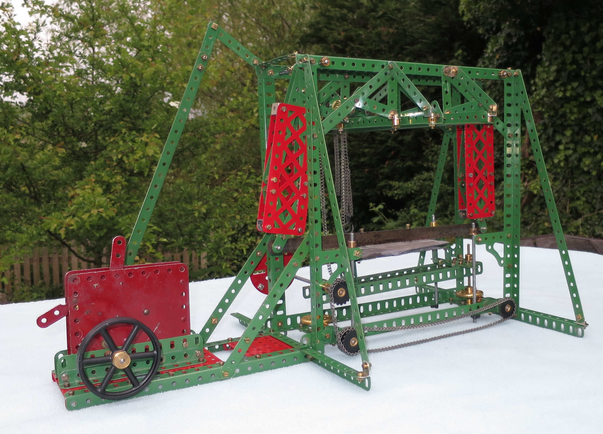
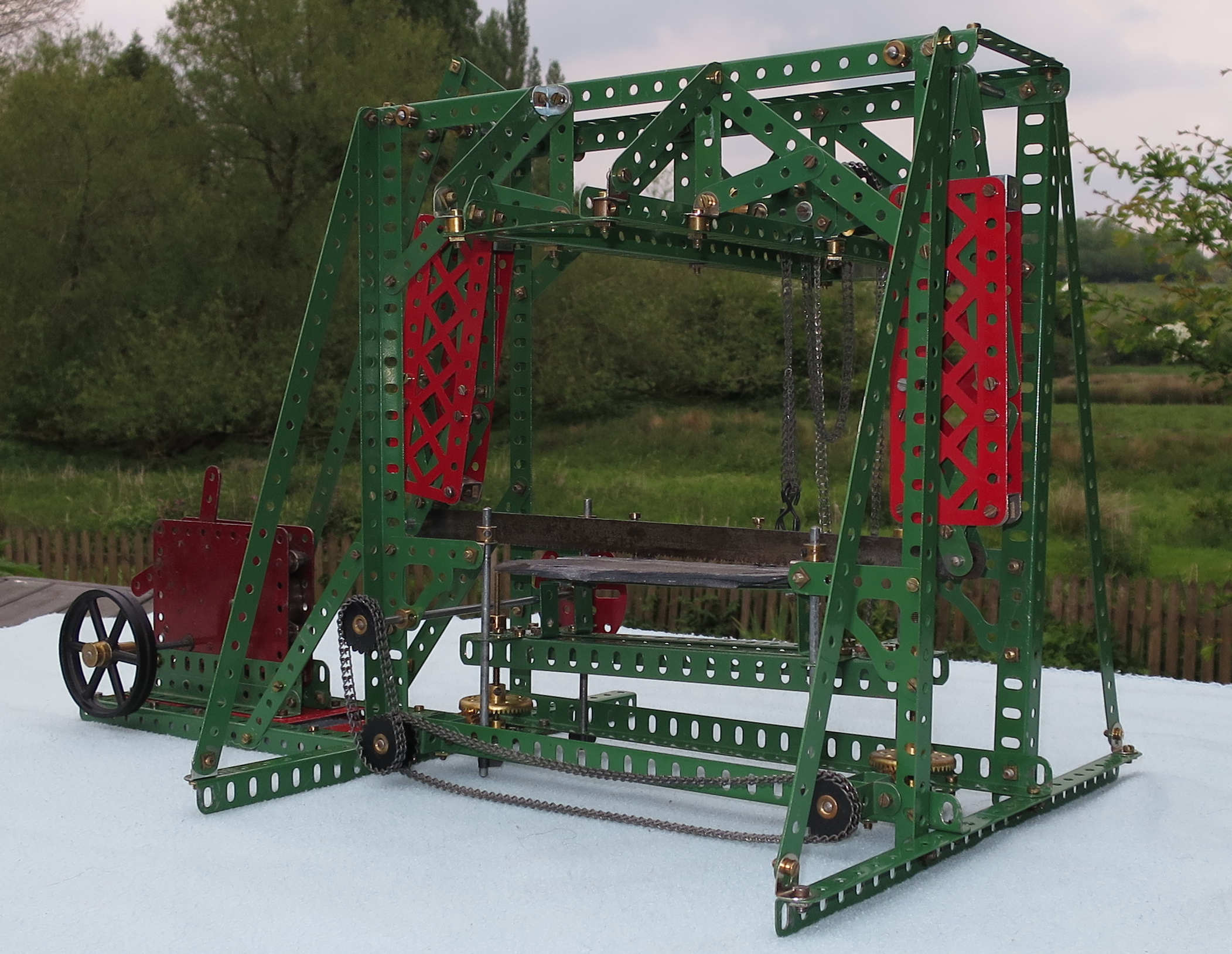
To get this model ready for an attempt to saw through rock, it needed toughening up. I was lucky enough to have an old hacksaw blade with holes 30cm apart that were a good fit for a Meccano rod, so that bit was easy. I already knew that a hacksaw blade would cut through slate, so I broke up a broken roofing slate to give me something the right size to saw. Here are the fixes I made to get it more or less working properly:

  1. The swinging frames were nowhere near rigid enough, giving a lot of lateral movement. To resolve this I added 3 more cranks to the top of the frames so each side of each frame was more rigidly attached to its rod. I also doubled up the set screws on the cranks on the right-hand side (rod 4, fig. 1).
  2. The blade wobbled. I fixed this by sandwiching the blade between two collars at each end.
  3. The motor was struggling to saw anything – it stopped as soon as the saw hit stone. I needed to improve the power getting through to the saw:
    • I extended the 12.5″ strip 6 (fig. 1) by 1.5″ using a 2.5″ strip. This gave better leverage.
    • I replaced 5″ rod 4 (fig. 1) with a 5.5″ rod, which allowed me to double up crank 5. With 2 set screws for each crank it stopped slipping on the rod.
    • I added a flywheel to give smoother running, which made a big difference. To do this I raised the motor up 0.5″ using 5.5″ flat girders, replacing the flat trunnion with a corner gusset. This was necessary to get the flywheel off the floor. I replaced the motor rod with a longer one (5″) and mounted the flywheel on the end. I could have added another corner gusset, but it would have added friction, so I didn’t.
  4. The work table needed a bit more flexibility, and I needed to prevent the blade coming into contact with the screwed rods. I raised the work table by 0.5″ by replacing the four 0.5″ reversed angle brackets (part 124) with 1″ reversed angle brackets (part 125). I moved the four corner gussets up one hole, and replaced the four 4.5″ guide rods with 5″ rods.
  5. The screwed rods kept jamming at their base, preventing the table from moving up and down smoothly. The threads were catching on the strips. I fixed this by replacing the two double bent strips with double arm cranks.
  6. To hold the slate in place I made two simple clamps from 0.5″ double brackets, 0.75″ bolts and a couple of nuts. My guess is that the prototype wouldn’t need clamps due to the weight of the stone being sawn, but some things don’t scale!

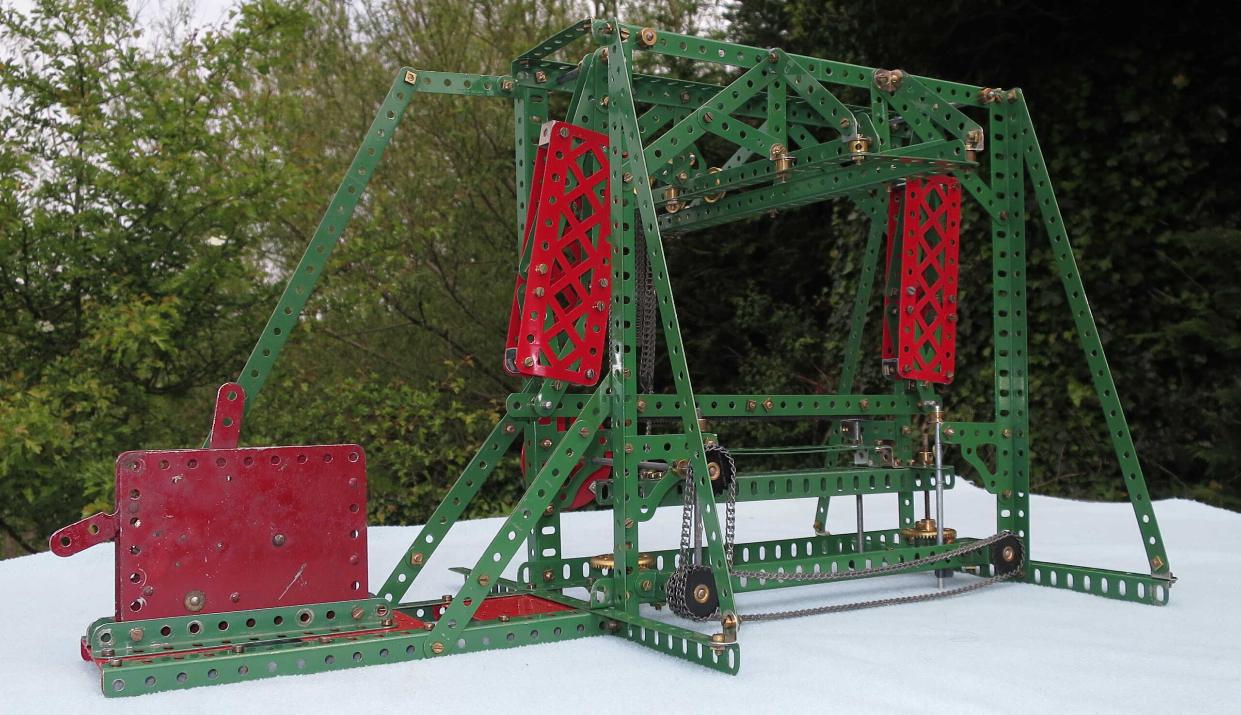
…and after all this the saw just about cuts through slate. Very slowly! More photos: