April 2026

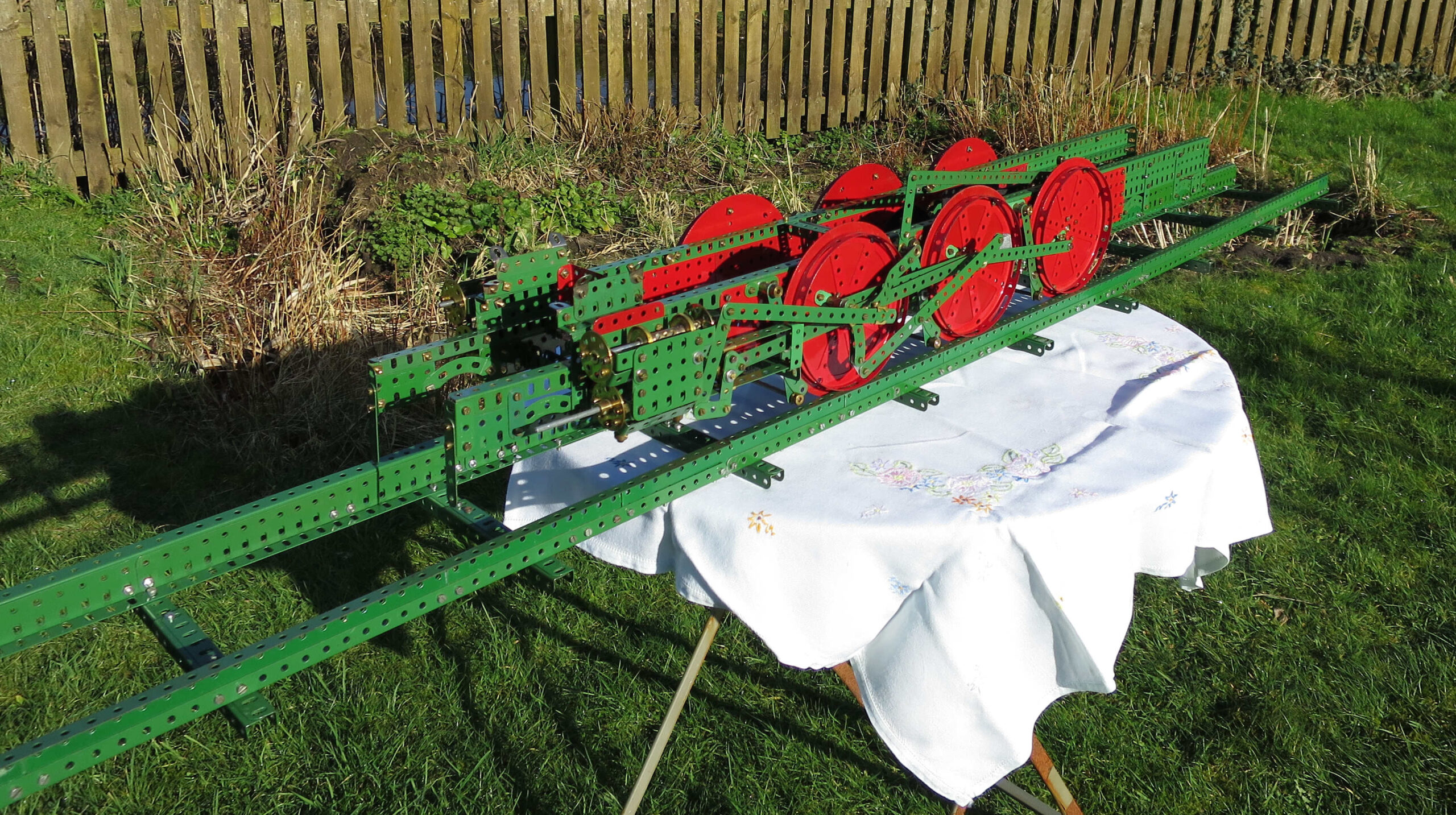
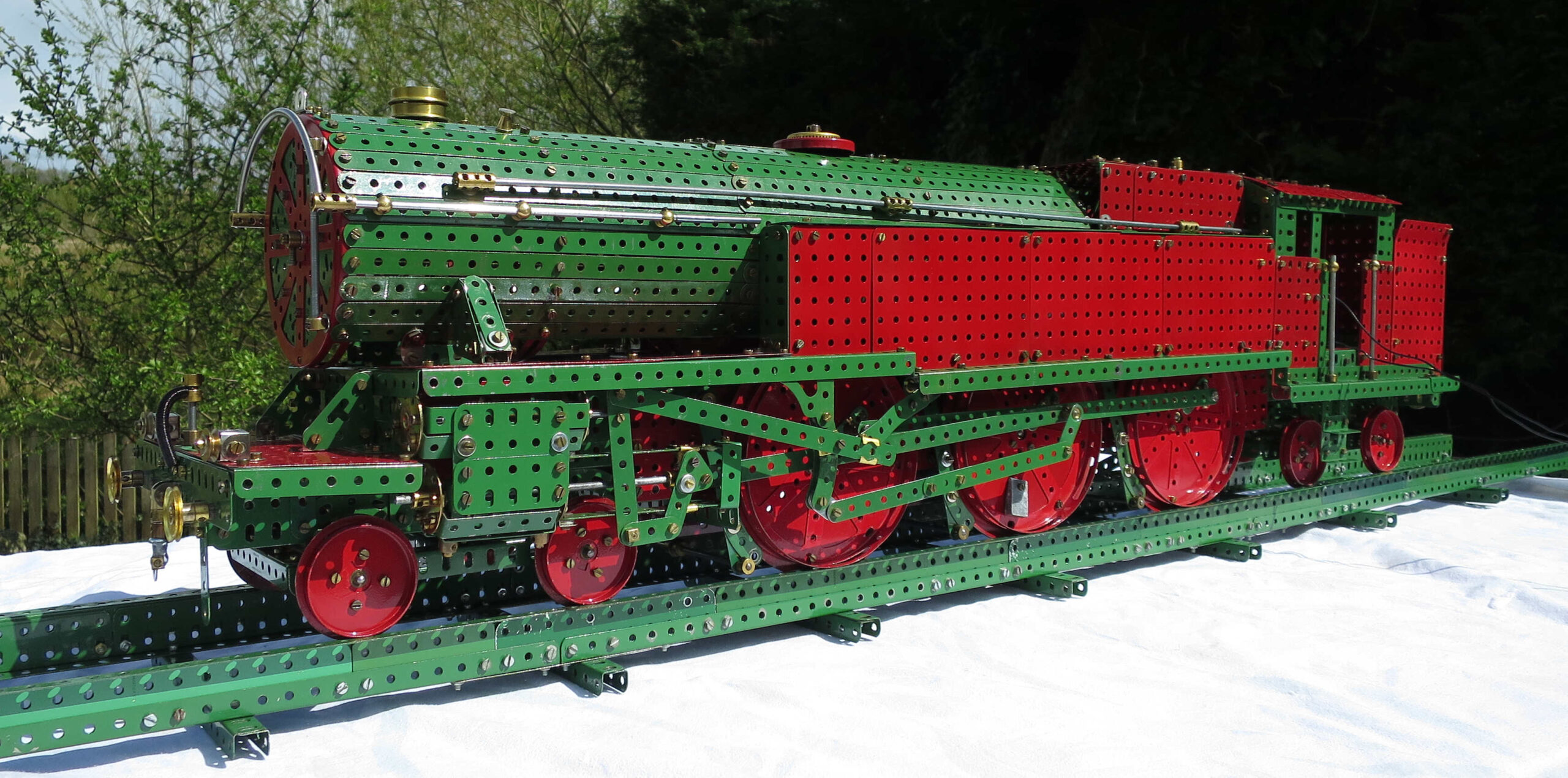
I completed this model at the end of March 2026, and took it to the Oxton meet on 25 April. It was big, nearly 4 ft long, and I had to buy more nuts and bolts to complete it. It looks great, and was fun to build. As far as practical I was faithful to the design instructions and illustrations in the 1928 Super Model leaflet as reproduced in Geoff Wright’s book.
As usual, the parts list was inaccurate in places, the instructions didn’t always match the pictures, and the pictures contradicted each other occasionally. All par for the course. One or two things in the instructions were clearly incorrect as well.
But, all the issues were pretty easy to resolve, and it’s a really good one to build. It’s one of the most visually attractive of the Super Models as shown in the leaflets (in my view), and that’s why it was high on my ‘must build’ list. The only snag holding me up was that to be faithful to the original I needed two 25 gramme weights (part no. 67), obsolete since 1940, and quite difficult to get hold of. Luckily a casual query from me resulted in John and Marie finding me a couple of original parts, for which I was very grateful.
Main build issues
- I had to bend quite a few strips and plates, and respray quite a few old plates too. I already had a strip bender, but I had to invest in a longer set of rollers to bend the plates. I can recommend John Thorpe‘s rollers.
- I don’t have the 4-volt motor used in the original model, and used a post-war E20R motor instead. This has a shorter frame than the pre-war 4-volt motor, so I needed to extend the frame with a couple of flat trunnions to hold the 2.5″ rod that carries 57-tooth gear 24. In the original model this rod also carries a 0.75″ pinion that engages with the 3.5″ gear on the axle for the middle driving wheels. This was trying to move the model too fast for my liking – I only had 6ft of track – so instead I journalled an additional rod in the main frames 2″ in front of the said axle. Instead of the 0.75″ pinion on the trunnion rod I fitted a 0.75″ sprocket, which drove 2″ sprocket on the additional rod. This rod also carried a 0.5″ pinion that drives the 3.5″ gear. This resulted in a speed reduction of about 3.4 times, which gave a more appropriate speed along the track.
- I was worried that the motor wouldn’t be capable of propelling the model, which weight about 25lbs. I was pleasantly surprised. Once I’d got everything lined up properly, oiled and greased appropriately, and fixed a design issue (described below), it worked very well. I doubled up all the set screws and grub screws on the main drive train, and bolted a 1.5″ pulley to the 3.5″ gear to give it 4 set screws in total.
- I modified the motor control lever slightly by extending the crank 96 with a 2 1/2″ strip. A 4″ made-up strip (as in the leaflet) connected to the left-hand motor switch tag worked a treat.
- The model needs 10 x 5.5″ flat girders, not 8 as given in the part list. Similarly it needs 9 x 2″ strips rather than 7, and 11 x 1″ rods rather than 7. Luckily I had them.
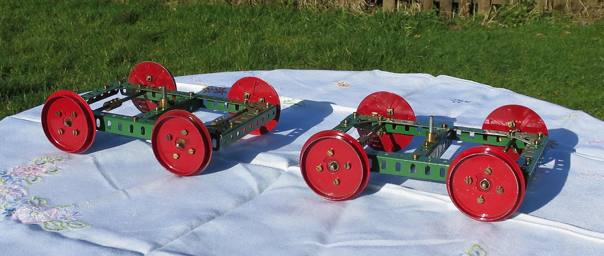
- The model as designed won’t run on rails, only on a flat surface. The bogie wheel flanges are 1/4″ smaller than those on the driving wheels, and when you put the model on rails this lifts the bogies higher and the bogie frames foul the main frames. To fix this I took the 7.5″ flat girders off the bogie frames and turned the 7.5″ angle girders round so I could journal the axles in the long holes of the girders.
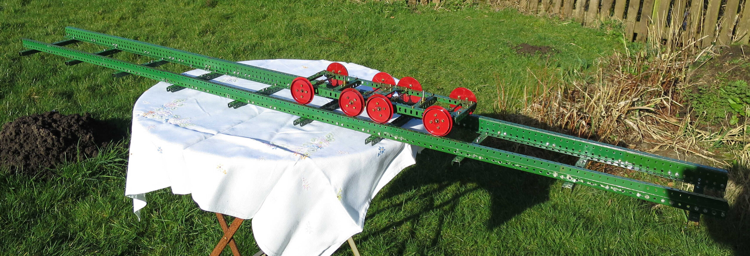
- The model still wouldn’t run on the rails shown in fig. 1 of the leaflet. The bolts securing the rails foul the driving wheel flanges. If you want it to really run on rails (as I did) then the rails need redesigning. I bolted two rows of flat girders onto the angle girders of the original rails, loosely bolted, wedged another row of angle girders between the flat girders, then tightened up the bolts until the angle girders were secure. I could probably have found a simpler solution, but this worked.
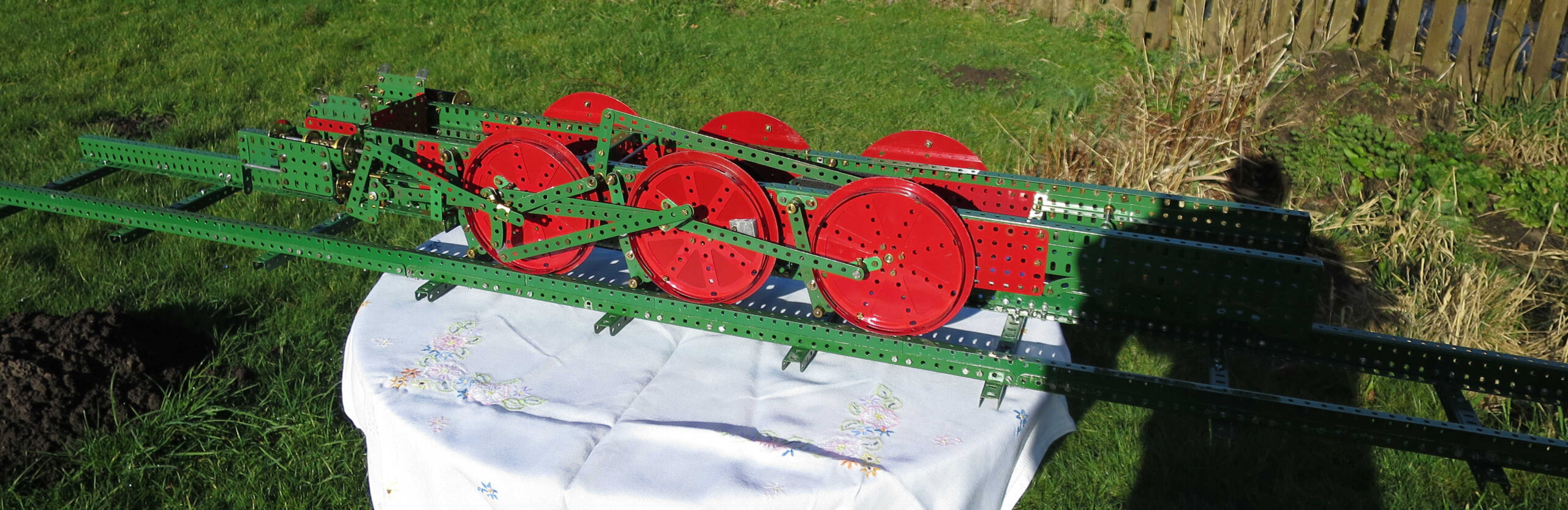
- The weigh shaft (see leaflet page 4 para 2) is specified as a 6.5″ rod, and this was too short. The 3.5″ strip 58 and its crank fouled coupling rods 48a and 49, with no obvious way of adjusting it. By using a built up 7.5″ rod instead, the 3.5″ strip and crank were now outside the coupling rods, and the problem went away.
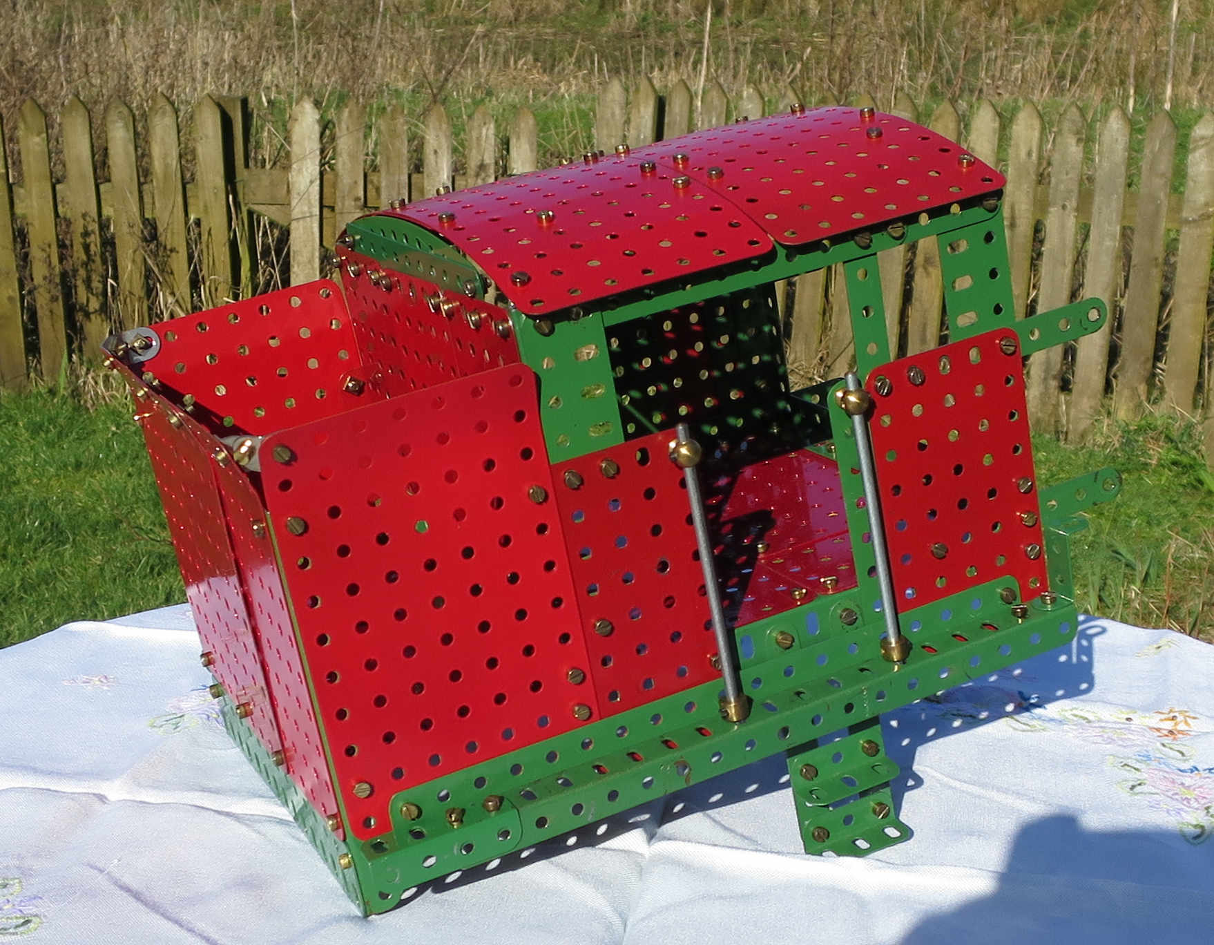
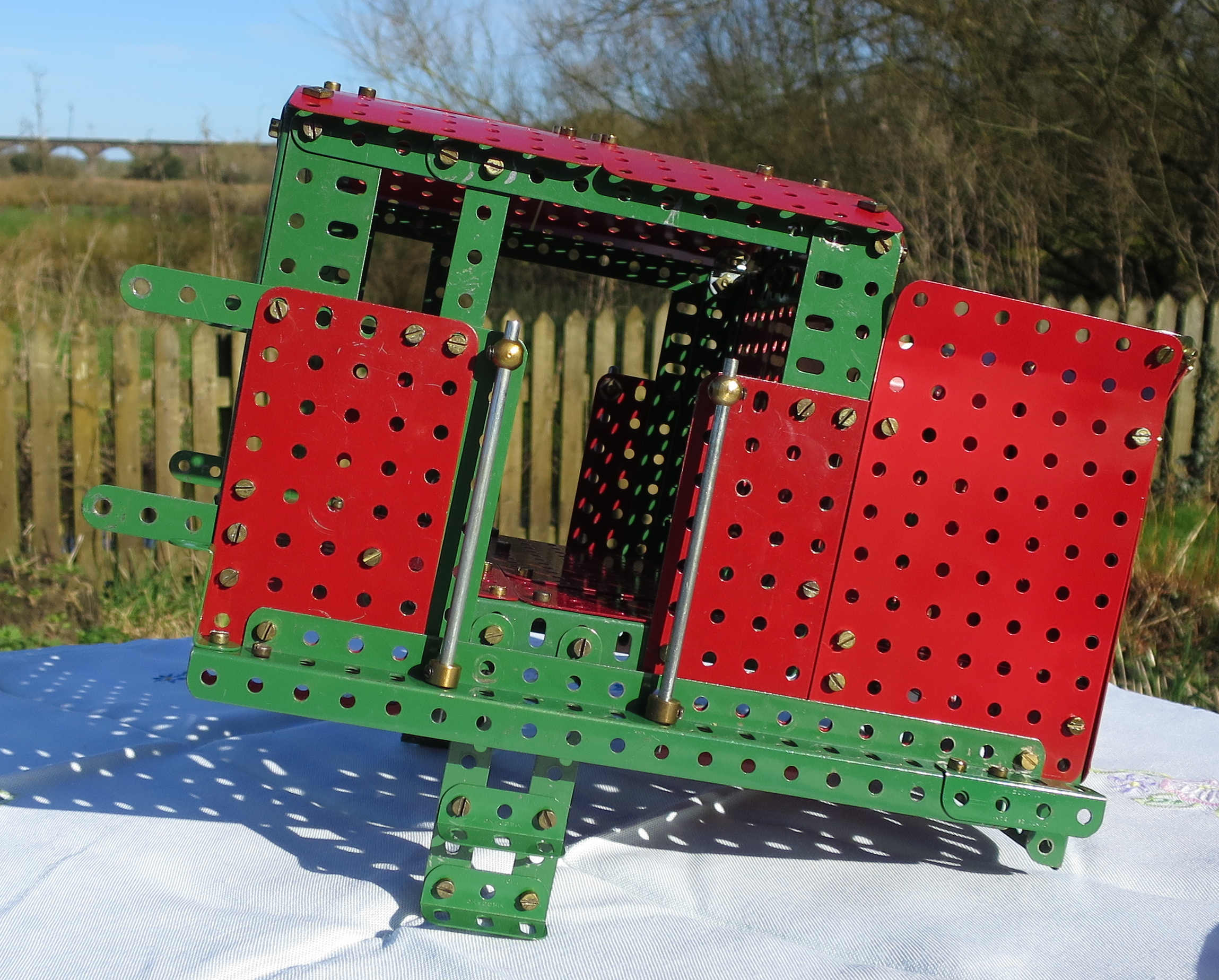
- The side handrails on the boiler are described as 8″ rods, but the illustrations clearly show 10″ rods, i.e. non-standard parts. I resolved this by extending the rods to 10″ with straight rod connectors and 2″ rods.
- The lamps can’t be built as described (page 5 para 4 of the leaflet), as far as I can see. The eye piece and double brackets can’t be bolted together like that, or at least I can’t do it. Instead of the eye piece I used a pair of angle brackets outside the double brackets to form the clip. I put a 0.75″ bolt through the long hole of one angle bracket, through one side of the double brackets, through the axle hole of a collar, then through the other side of the double brackets and the other angle bracket. Add a nut, adjust the clip to fit neatly on a lamp iron (i.e. another angle bracket) and tighten the nut. Put a washer, a 0.5″ pulley without boss and another washer on a 3/8″ bolt and screw it into the collar and you’re done.
- The front of the boiler isn’t shown in the leaflet. An earlier 4-6-2 version of the model appeared in Meccano Magazine, but it looks a bit ugly so I didn’t copy it. I just added a door handle centrally (a collar bolted to the central hole with another bolt in it for a handle), and a 3.5″ rod mounted vertically on collars on the RHS to represent the hinge.
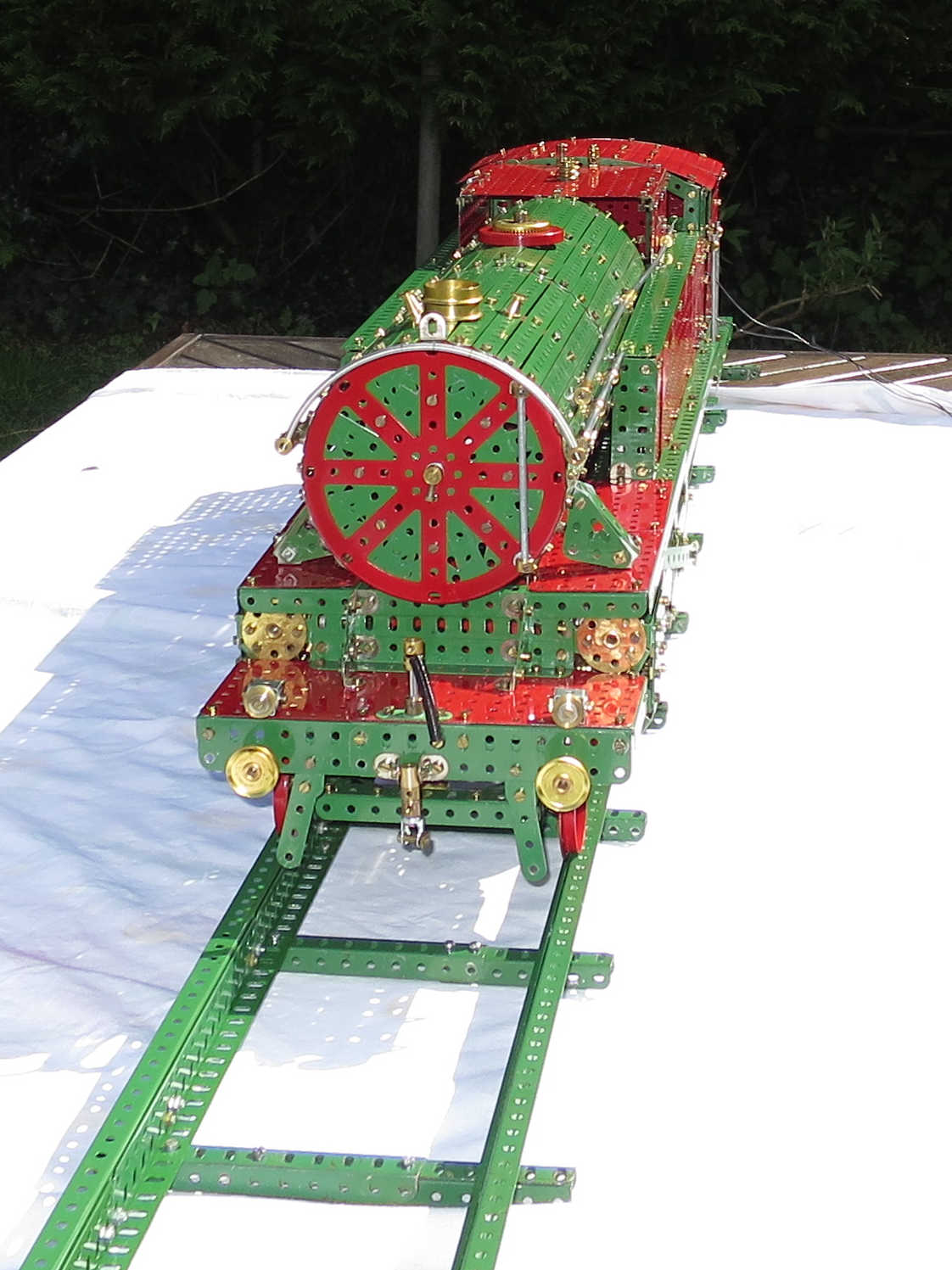
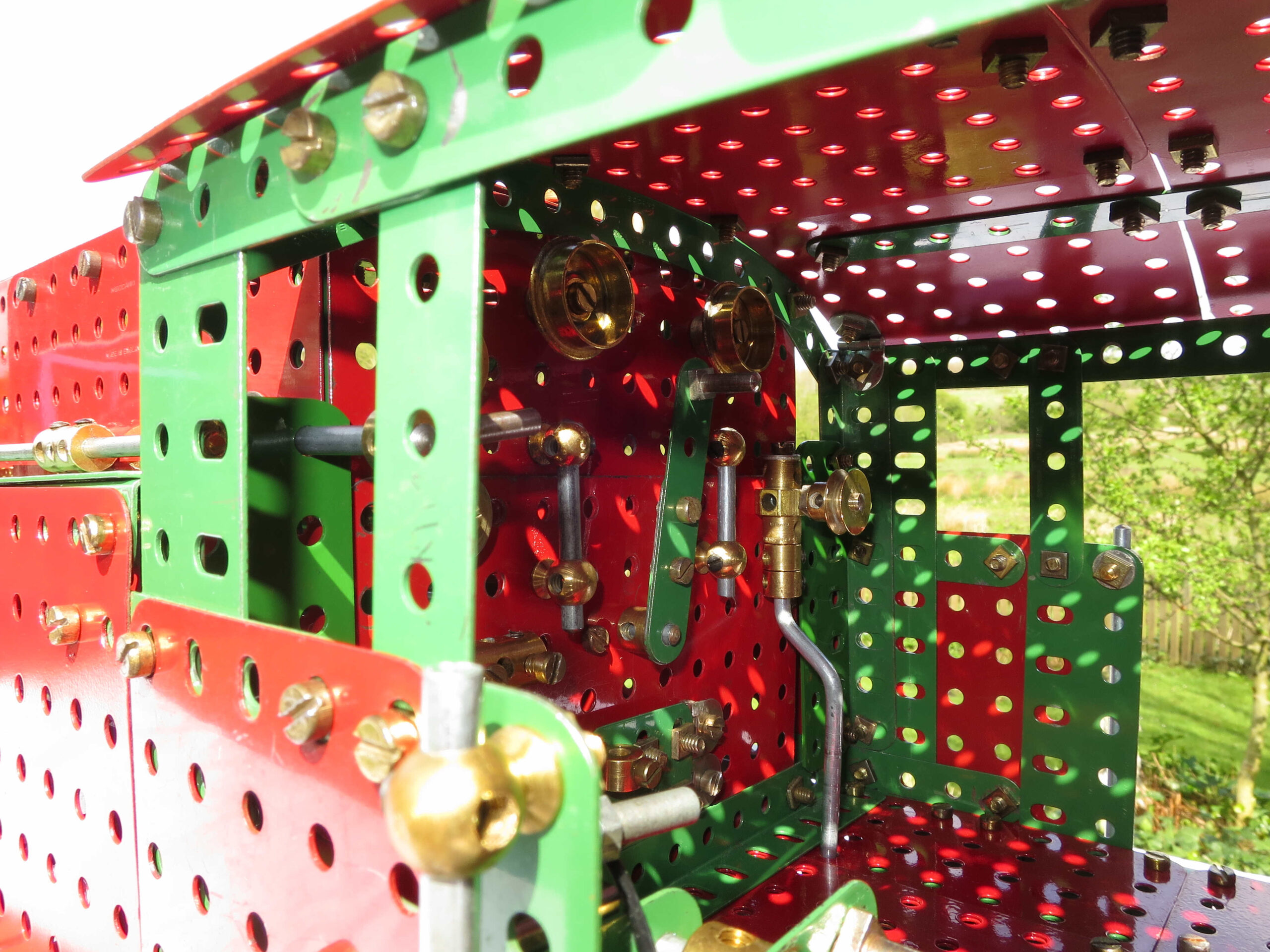
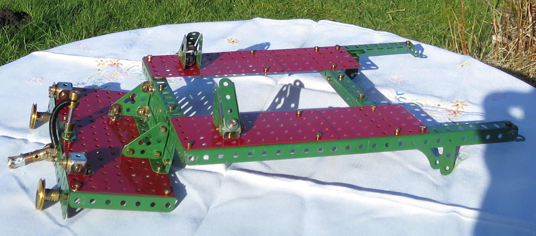
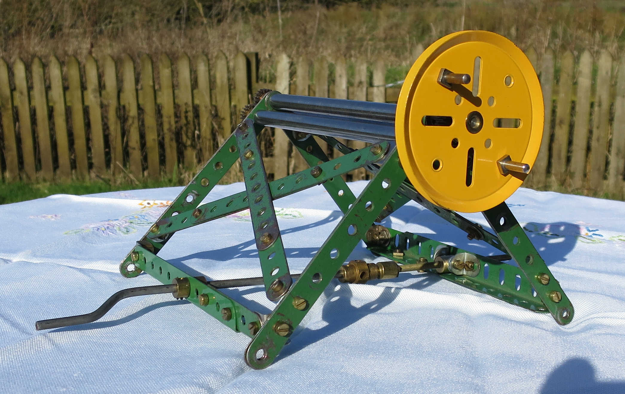
The photos below show some of the main units of the build as I was going along.