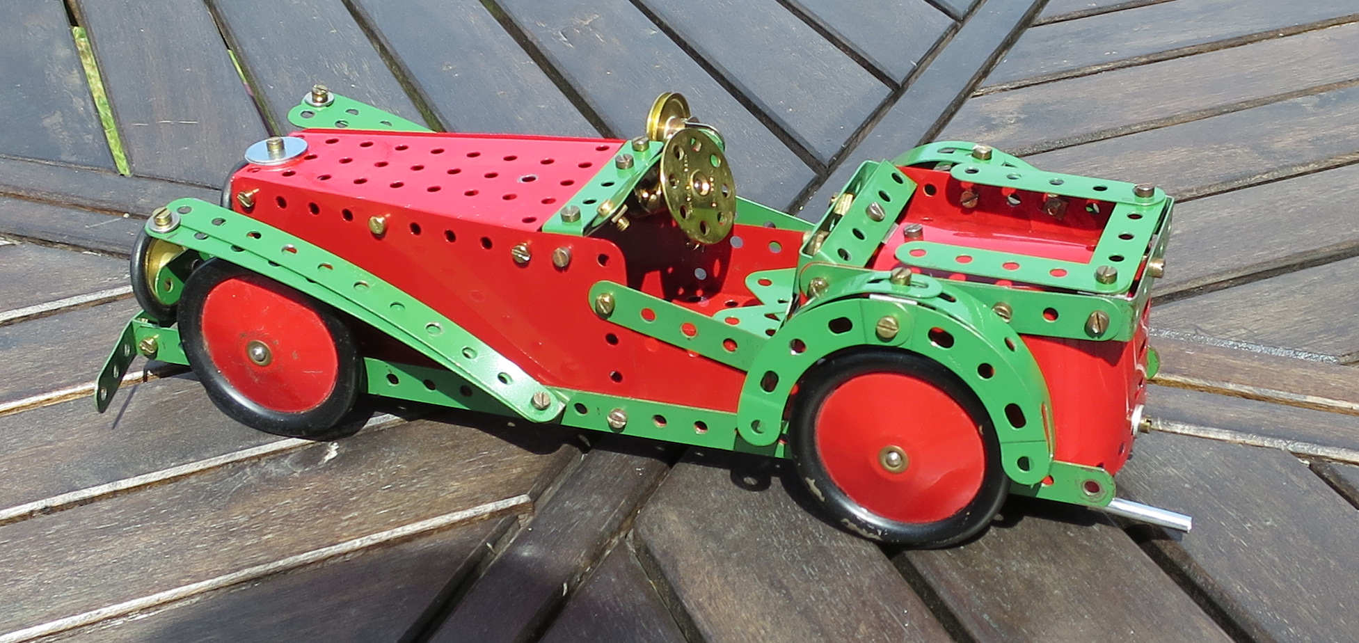
When I took my Super Model Motorcycle and Sidecar to bits it left a space on the mantelpiece that needed filling, so before I started on my next Super Model I built this little sports car from the 1938 Outfit 4 Instruction book. I’d seen Mei Jones’s collection of vintage sports car models at Gaydon 2026 and thought something along those lines would perhaps look good above the fireplace, and so it does.
As usual it’s built from post-war red and green Meccano and is pretty much as the Instruction book showed. I improved the way the wheels were fixed on to make them less wobbly, and never did work out why part 44 was on the parts list. It seems fine without it anyway.
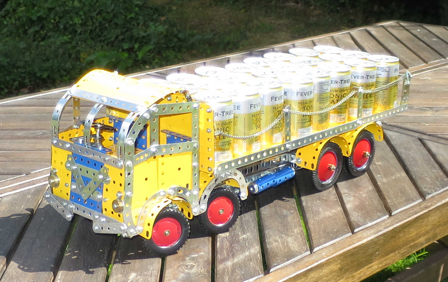
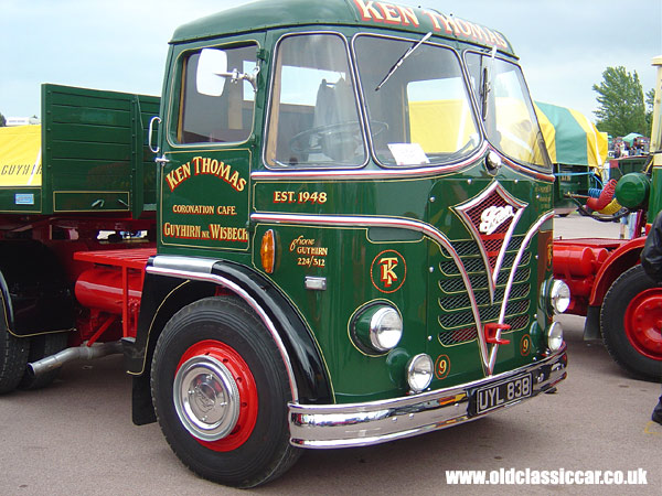
This is a model from the 1955 Meccano Instructions booklet for outfits 7 and 8. It’s numbered 8.19 in the booklet, and is titled ‘Eight-Wheeler Lorry’, but there can be little doubt that the prototype was a 1950s Foden lorry used for delivering barrels to pubs. Here’s a similar Foden cab:
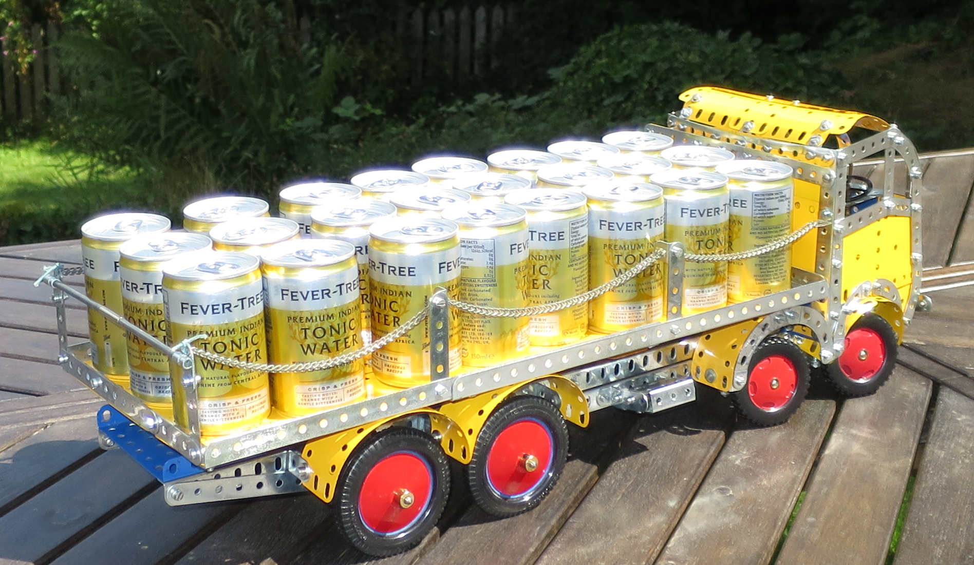
The model is built using my 1970s blue/yellow Meccano, and is pretty much as the instructions given in the booklet. There’s no suspension or cab floor, but that’s fair enough for an outfit 8 model I think. It looks pretty good, particularly once loaded up with tonic water. That won’t go to waste: I’ve got the gin to go with it.
The build was a bit fiddly in places. There are so many nuts inside the cab with no easy access to get your fingers or spanner in, whichever order you put the thing together. And the two front axles are 3 3/4″ apart, and as specified the rear of the two is significantly lower then the other 3 axles. This took a bit of sorting out. The latter issue I resolved by:
(1) I used 1″ by 1/2″ angle brackets to mount the axle rather than the 1″ by 1″ brackets, to take advantage of the long hole in the smaller brackets. I suspect this was the original intention and the text is incorrect, as the smaller brackets are on the parts list anyway.
(2) I also added a couple of washers to each of the double brackets, raising the axle up a bit more.
As for the non-standard distance between the axles, this matters because the steering needs a strip 3 3/4″ long between holes to keep the angles of the two sets of wheels synchronised. The leaflet does this with a 2 1/2″ strip and three fishplates bolted end to end, but this is just asking for trouble. They’ll just keep coming loose. Instead I used a 3 1/2″ strip, a 5-hole 2″ strip and a 2″ perforated slotted strip, which gave me a strip with holes the right distance apart that wouldn’t bend on me.
I’d already built a strip roller, but the rollers on that are only 3″ long. To build the Super Model no. 15, the Baltic Tank Locomotive, I was going to need a roller capable of bending plates 3 1/2″ wide. To be honest I wasn’t sure whether that could be done with Meccano, as it needs a lot of pressure to bend those plates. I decided to have a go anyway, although I had a fallback plan to use flexible plates instead if I couldn’t bend the rigid plates.
The 6″ rollers once more came from John Thorpe, and the roller was based on the design of my strip roller. I made this one a bit stronger, replacing the transverse strips with angle girders.
The roller works pretty well, considering it’s such a simple construction. I needed to bend two sets of 5 1/2″ by 3 1/2″ plates for the loco model. The first set was for the cab roof, and needed a fairly gentle bend across the whole plate. By very gradually increasing the bend in repeated rolls, I got a very good curve on the plates, and the roller didn’t explode. The second set of plates was for the top of the coal bunker, which needed a tighter curve, only at the end of the plates. Getting this tight curve was too much for the rolling machine – I just couldn’t roll the plate through the machine. What I could do though was to bend the plate without rolling it, then move it on a bit, then bend a bit more. That worked well enough to get the bends I needed.
I’d just add that the rollers themselves didn’t bend at all under the pressure. It was just too much for my Meccano. Thanks John!
As for bending an 8″ axle rod into a semicircle, which the loco also needed, I did that using a Workmate, a length of pipe and a pipe wrench!
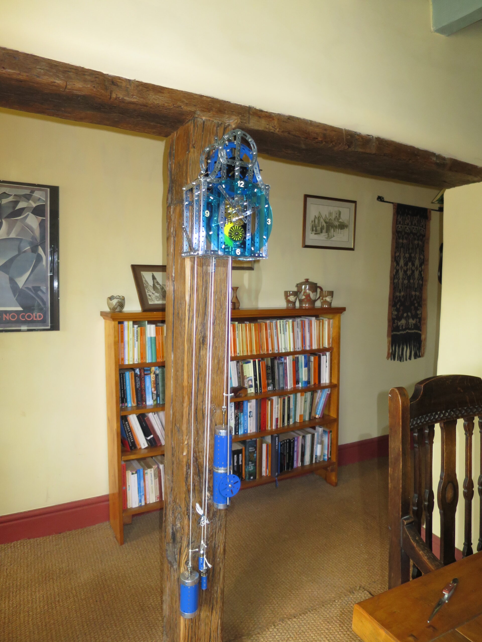
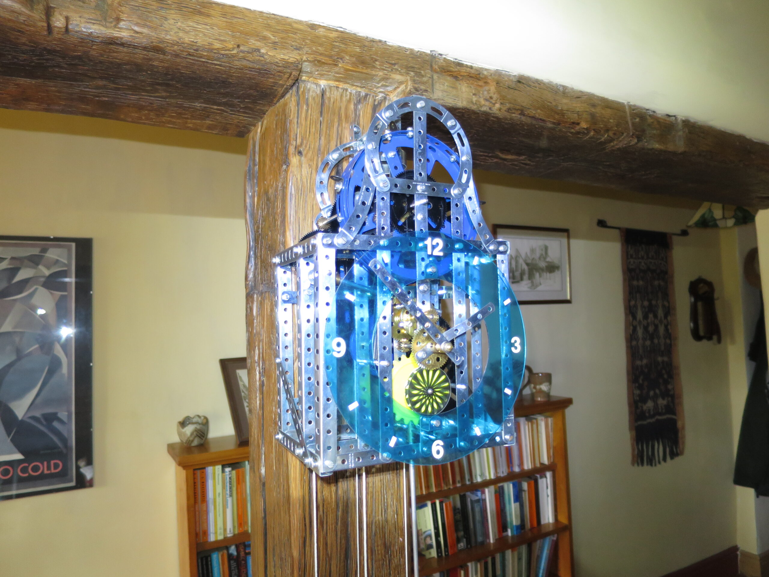
Spring 2024. The Meccano Clock Kit 2 was sold in the 1970s as a complete kit to build a striking clock using mainly standard Meccano parts. There was a handful of special parts included. I bought this back in the 1970s, built it once, then kept it. Now I’ve dusted it off and built it again. I can hear it ticking now as I type this. I keeps going for a couple of hours, until the weight hits the floor and it stops. If I mounted it in the stairwell to give the weight a longer drop, it would probably keep going for 8 or 12 hours, but it’s never going to manage 24 hours without ‘winding’. I say winding, but actually you have to raise the weights back up. It’s not particularly accurate! I’m still fettling it, as the striking isn’t working yet. It should strike once at 1 o’clock, twice at 2 etc. I may or may not eventually succeed at getting it to strike correctly.
Update Summer 2025. I’ve still not come back to work on this to get the strike working. This is due to a nasty accident in July 2024, which put me out of action for a year, as far as Meccano is concerned anyway. I’m back in action now, but concentrating on building a Meccano loom. I’ll be back to get the clock sorted after the loom’s finished!
Update May 2026. I gave getting the striking working properly another go, but having to stand up to work on this one was giving me quite a lot of chest pain, so I gave up on it for now. Maybe I’ll come back to it at some point and rebuild it.
Build notes
Not much to say, other than it needs a lot of fiddling to get it working properly. And sparing application of light machine oil.
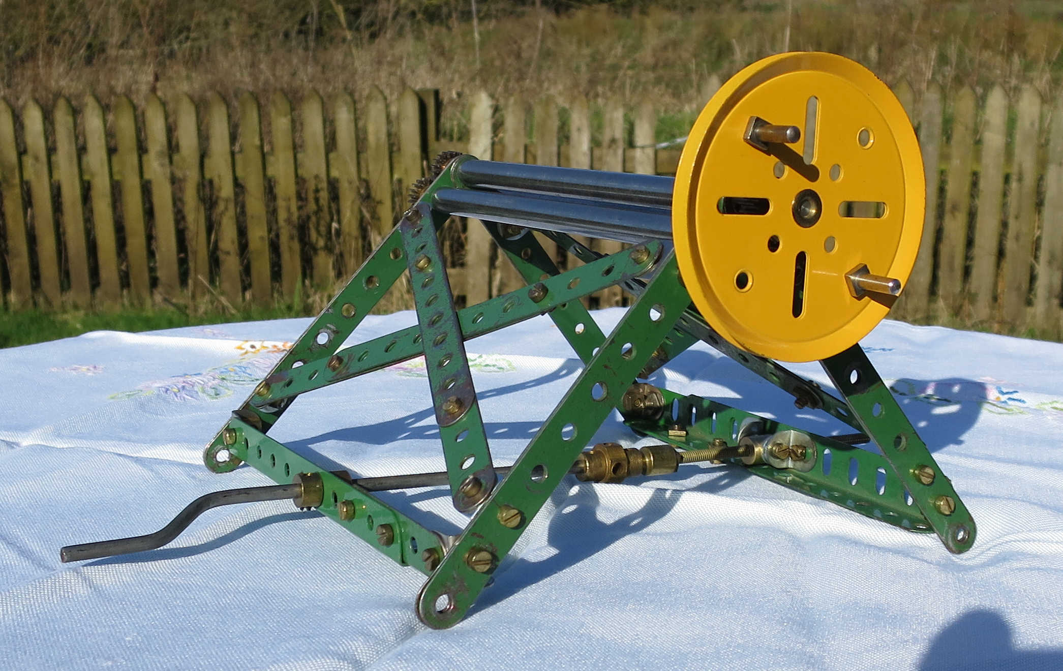
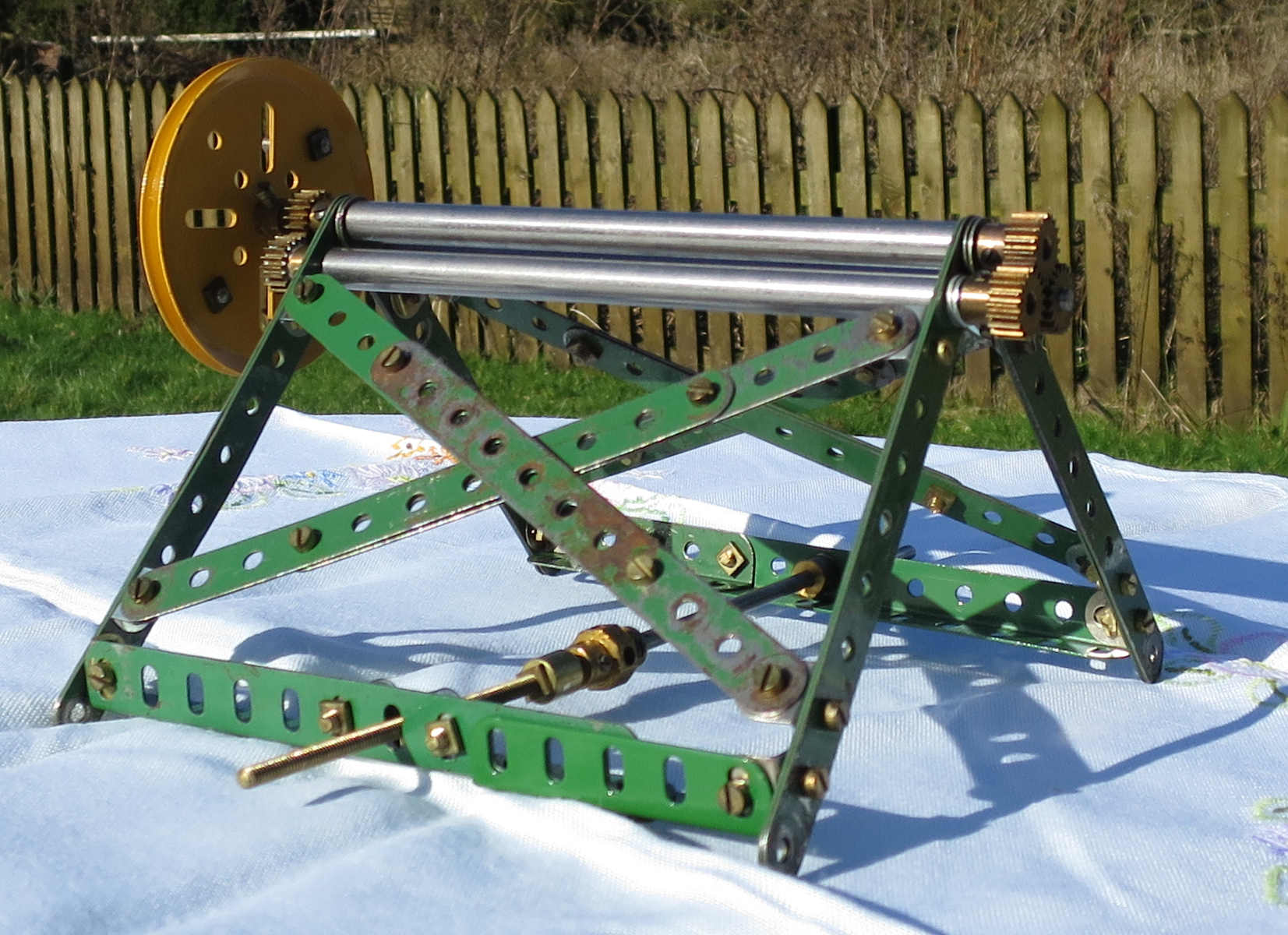
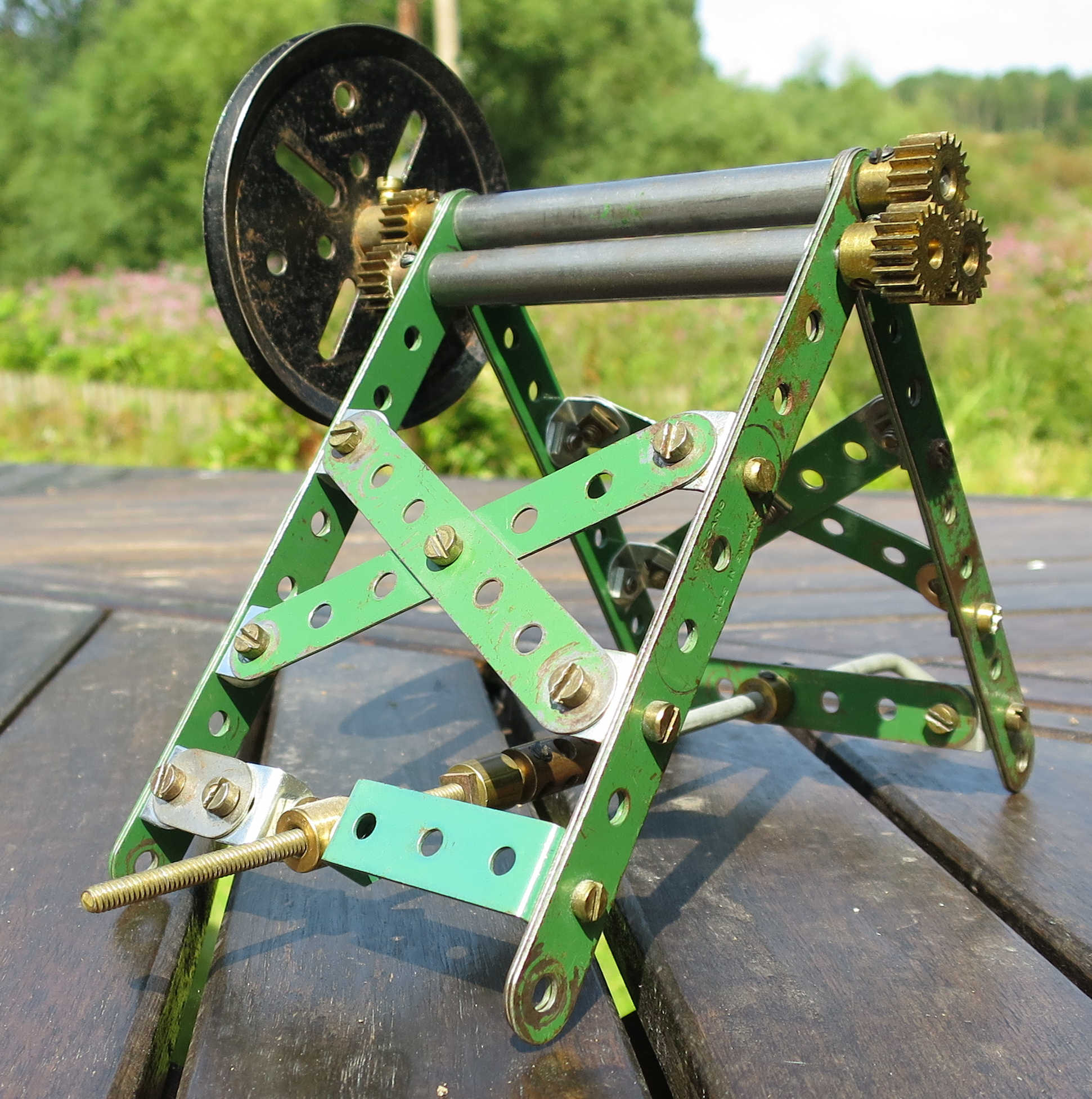
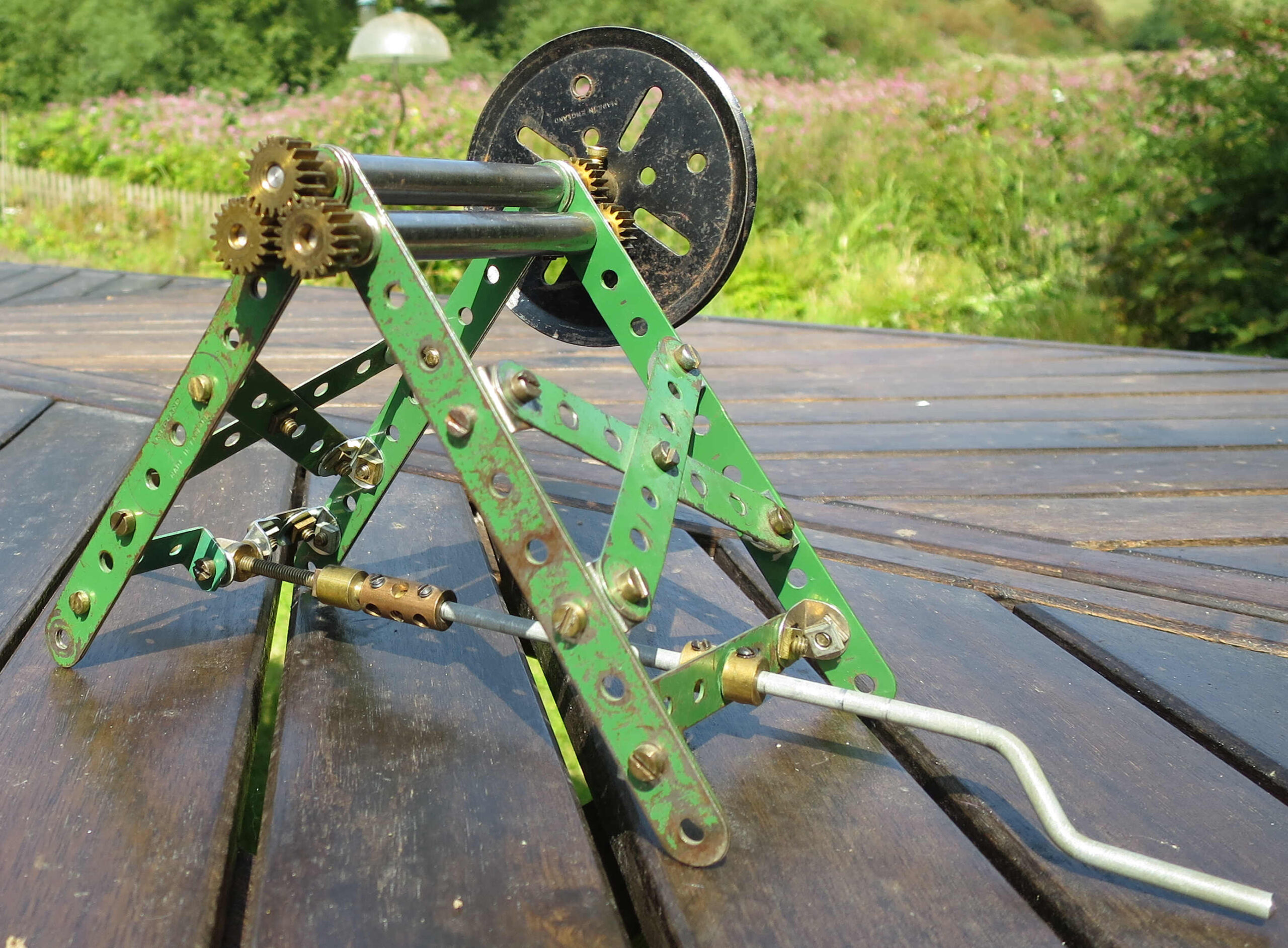
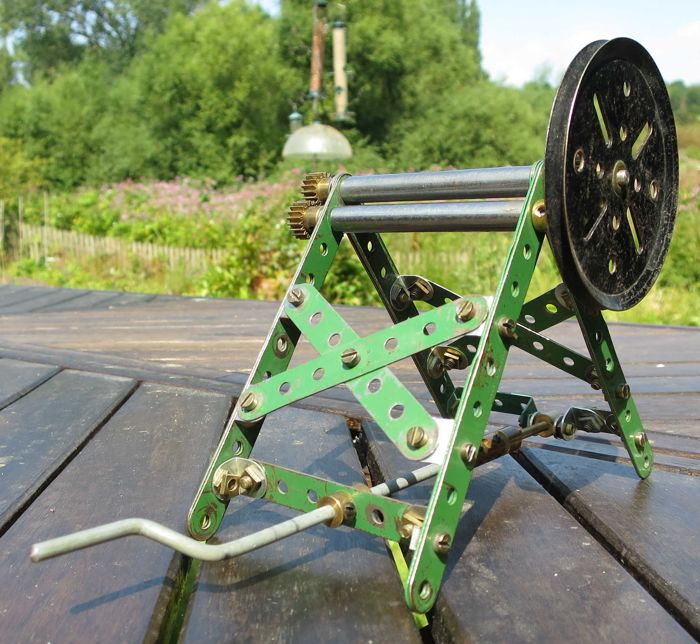
Updated Summer 2025: This is a tool rather than a model, and is now working pretty well. I’ve had to bend quite a few strips and flexible plates, and I’d rather bend them smoothly if I can. They last longer and look better that way. So I bought a set of steel rollers that should enable me to build a rolling mill for strips, plates up to 2.5″, and even flat girders, I hope. Initially I couldn’t get enough power to the rollers, as whatever I fixed to the end of the driving roller to drive it just slipped. I ended up filing flats onto the end of the driving roller shaft, which did the trick. I’ve just used it for strips so far, including longer ones (which are a bit thicker than the shorter ones).
I’m not actually keen on filing flats onto rods, as they only seem to hold temporarily – the screws work loose after a short while. For that reason I’m not intending to file any flats on the rods on my loom, if I can possibly avoid it.
The roller was based on one built by Arup Dasgupta, which itself was based on earlier designs. Mine is more robust due to the doubled 5 1/2″ strips and doubling the pinions up. A tyre on the pulley doesn’t work: it will slide round.
Parts list: 8 x 2, 4 x 3, 1 x 4, 1 x 10, 12 x 12, 1 x 19b, 1 x 19h, 6 x 26, 4 x 48, 2 x 59, 1 x 63, 1 x 64, 1 x 80c, 1 x 173a, plus nuts and bolts and a set of 3″ rollers, which I sourced from John Thorpe.
The crank is made up from a long crank handle extended with a 3″ screwed rod by means of a coupling and an adaptor for screwed rod. The screwed rod runs through a threaded boss that’s hinged onto a 1 1/2″ double angle strip and a 1″ double angle strip (made up from a fishplate and 2 angle brackets).